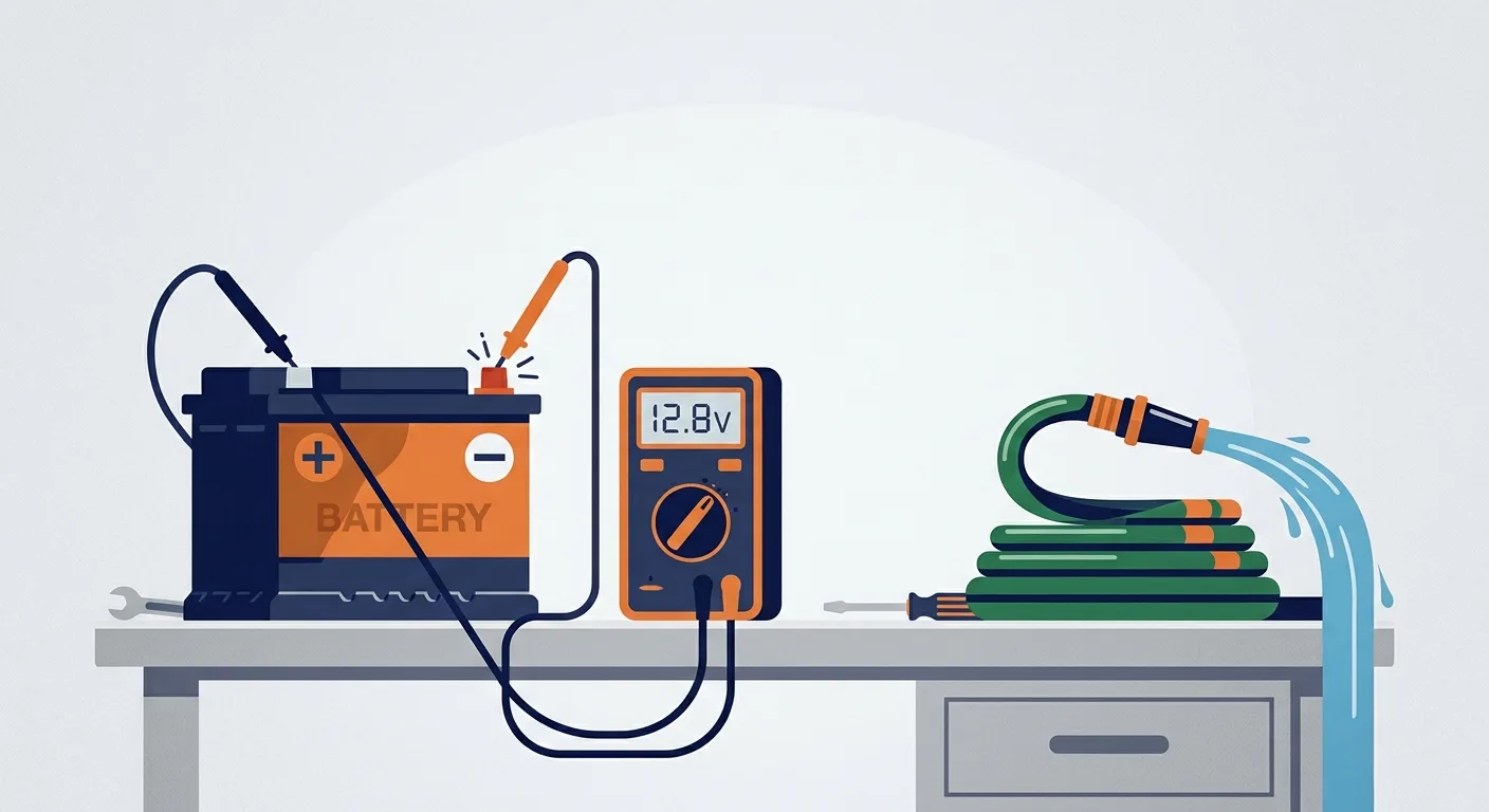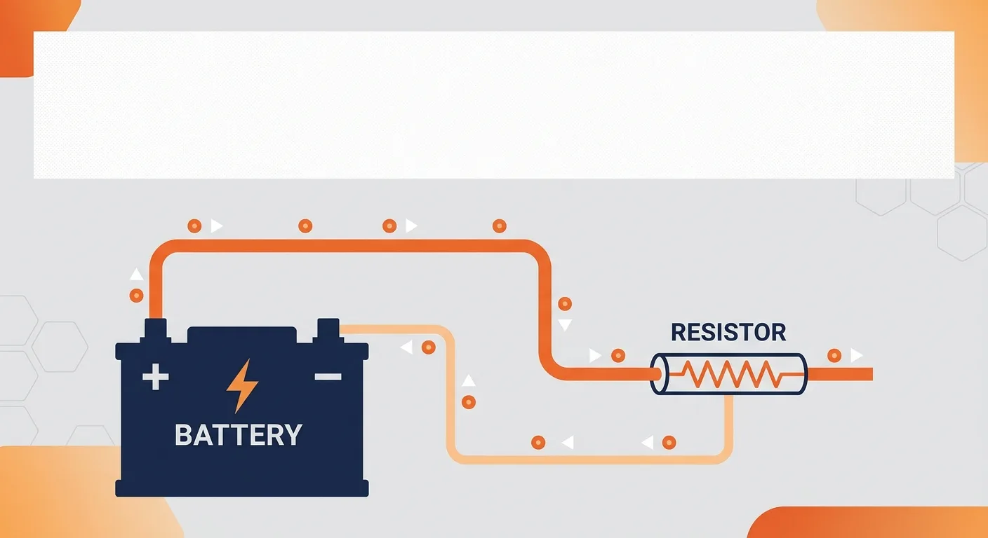
Picture water moving through a pipe. The pump creates pressure, the water flows, and a narrow section of pipe slows it down. That narrow section is resistance. It is a decent picture, and it breaks down fast: electrons do not behave like water, current does not "get used up" as it flows, and a wire is not a pipe. Still, the analogy gets you through the first hour of learning electricity, which is what it is for.
By the end of this article you should be able to look at a simple circuit and work out voltage, current, resistance and power with nothing but a pen and Ohm's law. We will go through the four quantities, the formulas, series and parallel wiring, the difference between DC and AC, and how to measure any of it without damaging your meter or yourself.
The four quantities
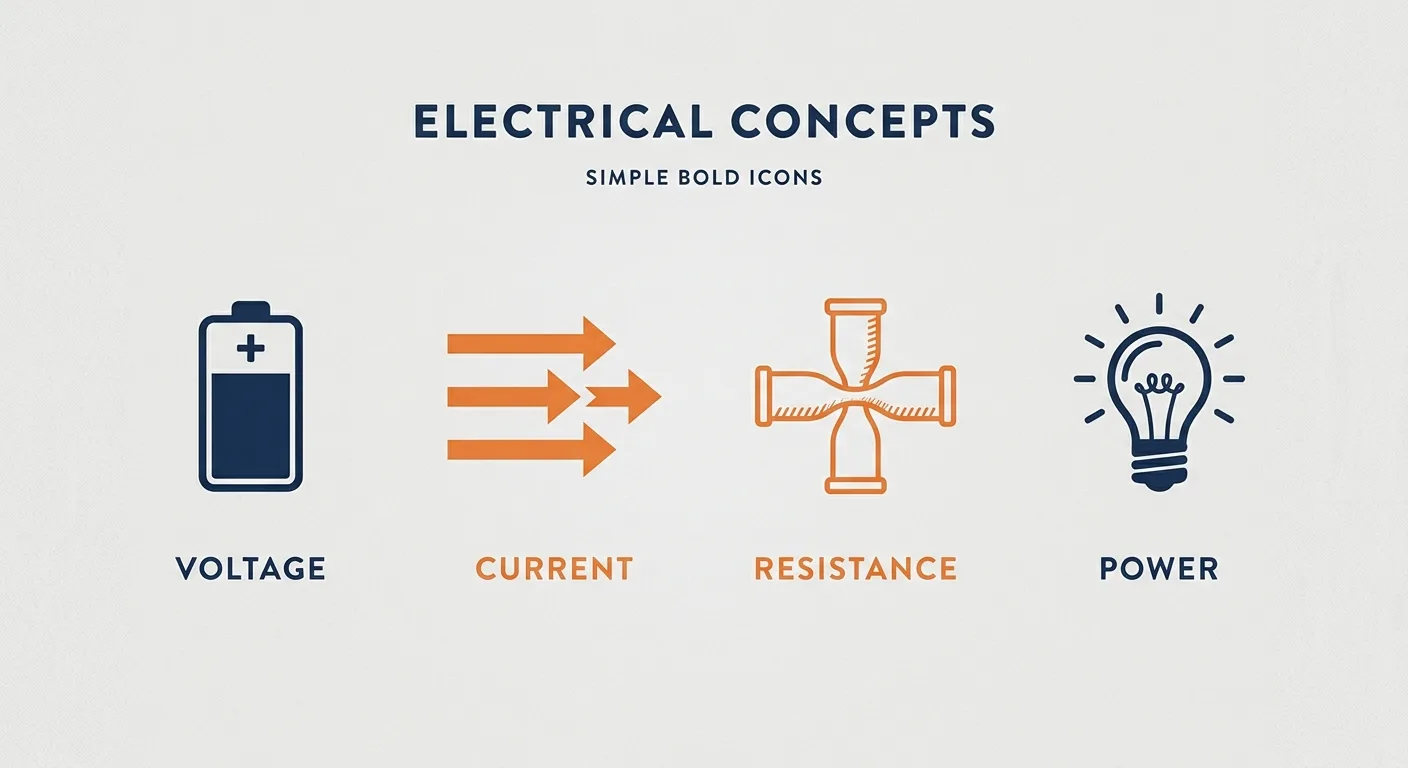
Four words carry most of basic electricity. Learn them properly and the rest is arithmetic.
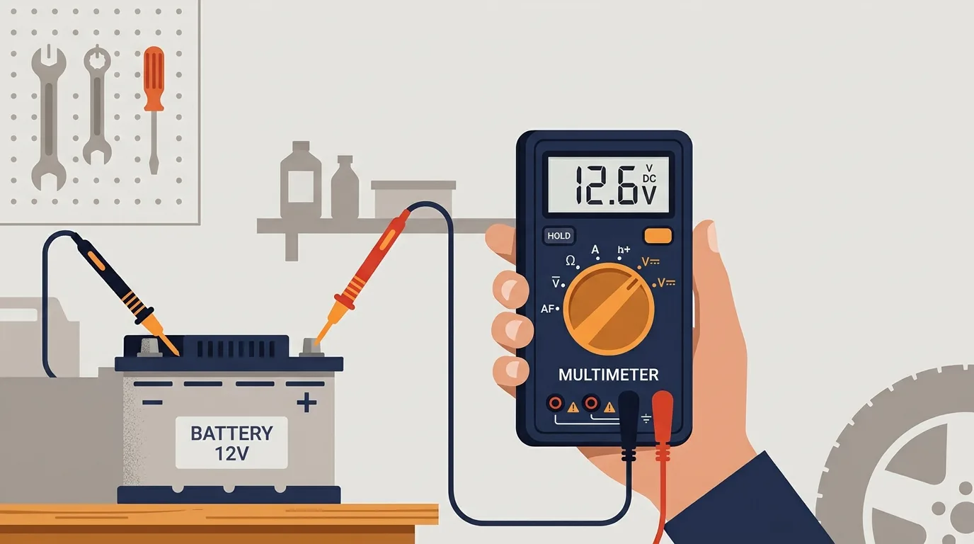
Voltage (symbol V, unit the volt, V) is potential difference. It is the "push" available to move charge between two points. A healthy 12 V car battery sits around 12.6 V at rest; a fresh AA cell is about 1.5 V. Voltage is always measured across two points, never through a component.
Current (symbol I, unit the ampere, A) is the rate at which charge flows. One ampere is one coulomb of charge passing a point per second. A small dashboard bulb might draw around 0.5 A; a starter motor can pull hundreds of amps for a second or two. Current flows through a component. That distinction matters later when you pick a multimeter mode.
Resistance (symbol R, unit the ohm, Ω) is how much a component opposes current. A short, thick copper cable is a fraction of an ohm. A small indicator lamp filament is tens of ohms when hot. Resistance converts electrical energy into heat, which is the whole point in a heater and an unwanted side effect in a connector.
Power (symbol P, unit the watt, W) is energy transferred per second. A 12 V, 5 W tail light and a 12 V, 55 W headlight run at the same voltage but the headlight moves eleven times the energy each second.
Note the pattern: voltage is measured between two points, current is measured through a path. Mixing those up is the most common beginner mistake at the meter.
Ohm's law and power

Ohm's law ties the first three quantities together:
- V = I × R
- I = V / R
- R = V / I
Power adds two more:
- P = V × I
- E = P × t (energy in joules, where t is time in seconds)
All the examples below are illustrative, not taken from any vehicle or product. Do the arithmetic along with me.
Example 1: 12 V across 3 Ω. Use I = V / R. So I = 12 / 3 = 4 A. The resistor dissipates P = V × I = 12 × 4 = 48 W. That is a lot of heat in a small part, and it tells you the resistor had better be rated for it.
Example 2: a 60 W load on 12 V. Rearrange P = V × I to I = P / V. So I = 60 / 12 = 5 A. That is the current the wiring has to carry, so the fuse and cable need a comfortable margin above 5 A.
Example 3: find the resistance. Suppose the same 12 V source pushes 0.25 A through a lamp. Then R = V / I = 12 / 0.25 = 48 Ω. If the lamp runs for 30 seconds, energy used is E = P × t = (12 × 0.25) × 30 = 3 × 30 = 90 J.
Round sensibly. Real components have tolerances, and a meter reading of 47.8 Ω on a nominal 48 Ω part is normal.
Series and parallel
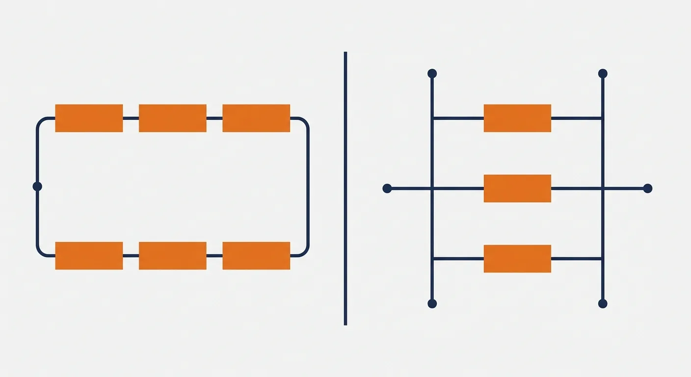
Series means one path. The same current flows through every component, and the voltages add up. Resistances simply add: R_total = R1 + R2 + R3. If one part fails open, everything downstream goes dead.
Parallel means multiple paths across the same two points. The voltage is the same across each branch, and the currents add. The resistance formula is the reciprocal one: 1 / R_total = 1 / R1 + 1 / R2. For two resistors there is a shortcut: R_total = (R1 × R2) / (R1 + R2).
Short worked example: two 6 Ω resistors in parallel. R_total = (6 × 6) / (6 + 6) = 36 / 12 = 3 Ω. Doubling up halved the resistance, which is why parallel paths carry more current.
This is why almost every vehicle and household load is wired in parallel. Each device sees the full supply voltage, and switching one off does not kill the rest. Your headlights do not dim because the radio is on.
DC and AC
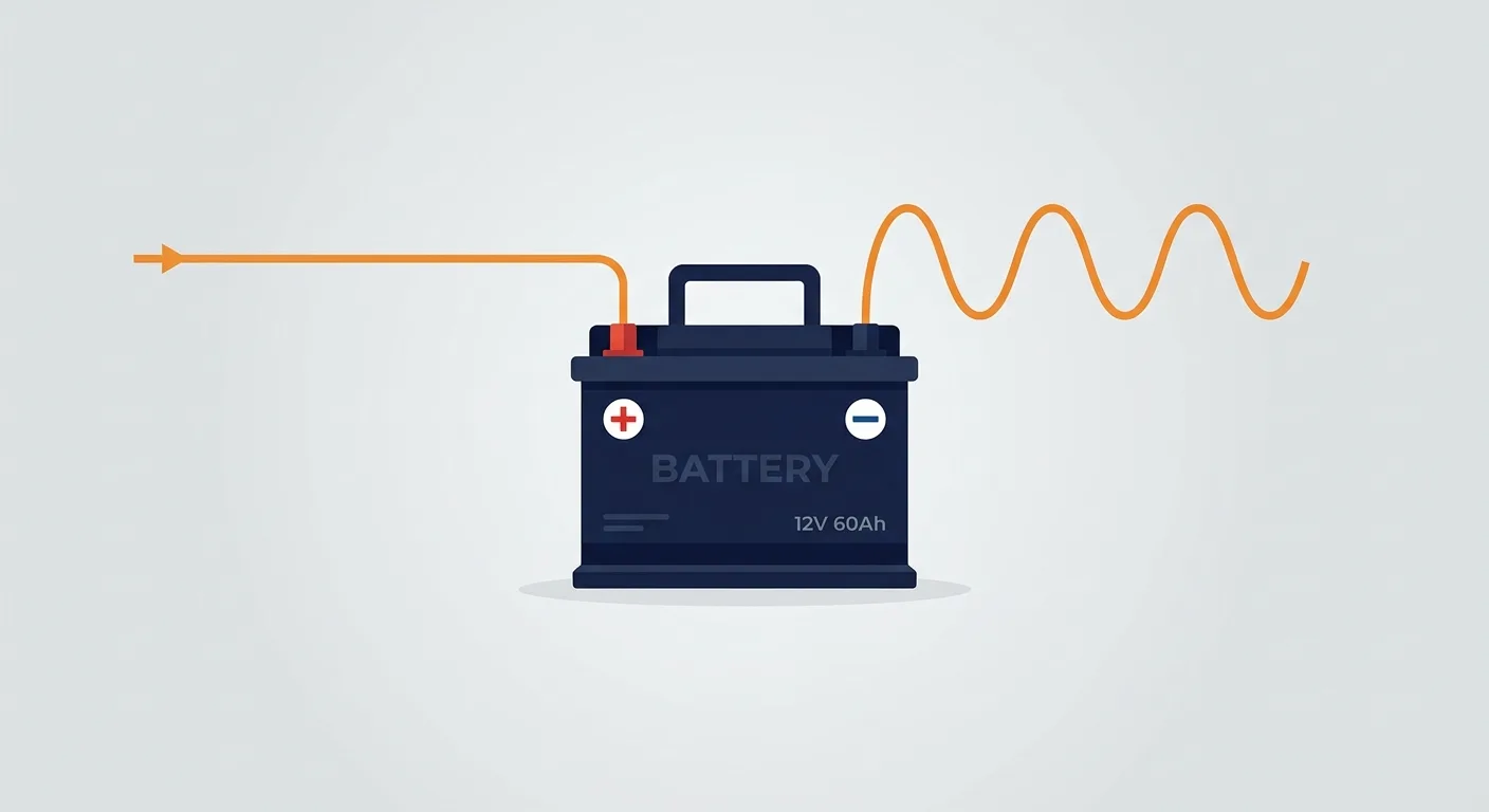
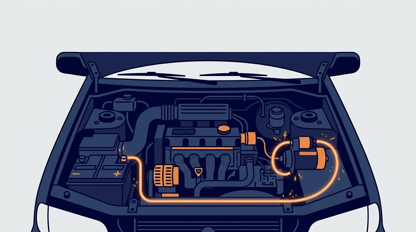
Direct current (DC) flows one way at a steady voltage. A car runs on low-voltage DC: nominally 12 V, with the charging system pushing around 13.5 to 14.5 V when the engine is running. It is safe to touch the terminals in normal circumstances, but a short across a battery can still burn you, melt wiring or start a fire, so treat it with respect.
Alternating current (AC) reverses direction many times a second. Frequency is how many complete cycles happen per second, in hertz (Hz). Mains in most of the world is 50 Hz or 60 Hz depending on the country; check your local supply rather than assuming. AC is used for distribution because transformers can step it up and down efficiently, which is not practical with DC at scale.
The safety point is simple: low-voltage DC is within reach of a careful beginner. Mains AC is not. Faults there can be lethal and can start fires inside walls. Leave it to a qualified electrician.
Measuring safely
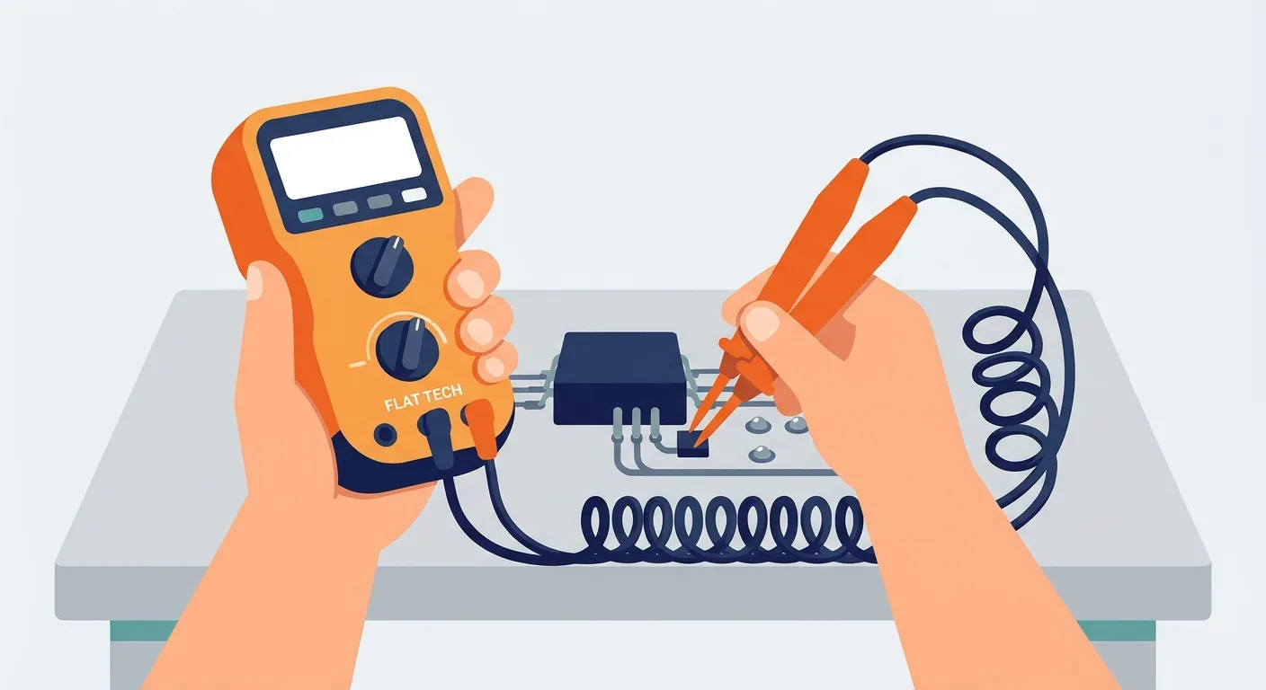
A multimeter is the right tool, and mode selection is where beginners get hurt or buy a new meter.
- Voltage (V): probes go across the component, in parallel with it. The meter has a high internal resistance so it barely affects the circuit.
- Current (A): the meter must be placed in series, so the current flows through it. That means breaking the circuit. Choose the correct range before connecting, and use the fused current input. A current range that is not fused, or is fused for too little, will die the moment you put it across a battery.
- Resistance (Ω): only on a dead circuit. Disconnect the supply and, if there are capacitors, let them discharge first.
- Continuity: a beep to confirm a path exists. Handy for checking grounds and broken wires.
The rule that keeps you out of trouble is test before touch. Prove the meter works on a known live source, test the circuit, then prove the meter again. If the meter is faulty you will find out before you trust it on a dead circuit.
For mains work, use a meter with an appropriate category rating for the environment, and adopt one-hand practice so current cannot cross your chest. That is the limit of what this article will tell you: mains work belongs to a qualified electrician.
Common misconceptions
Voltage is not current. A 12 V supply can push 1 mA or 100 A depending on the load. Voltage is the push; current is what actually flows.
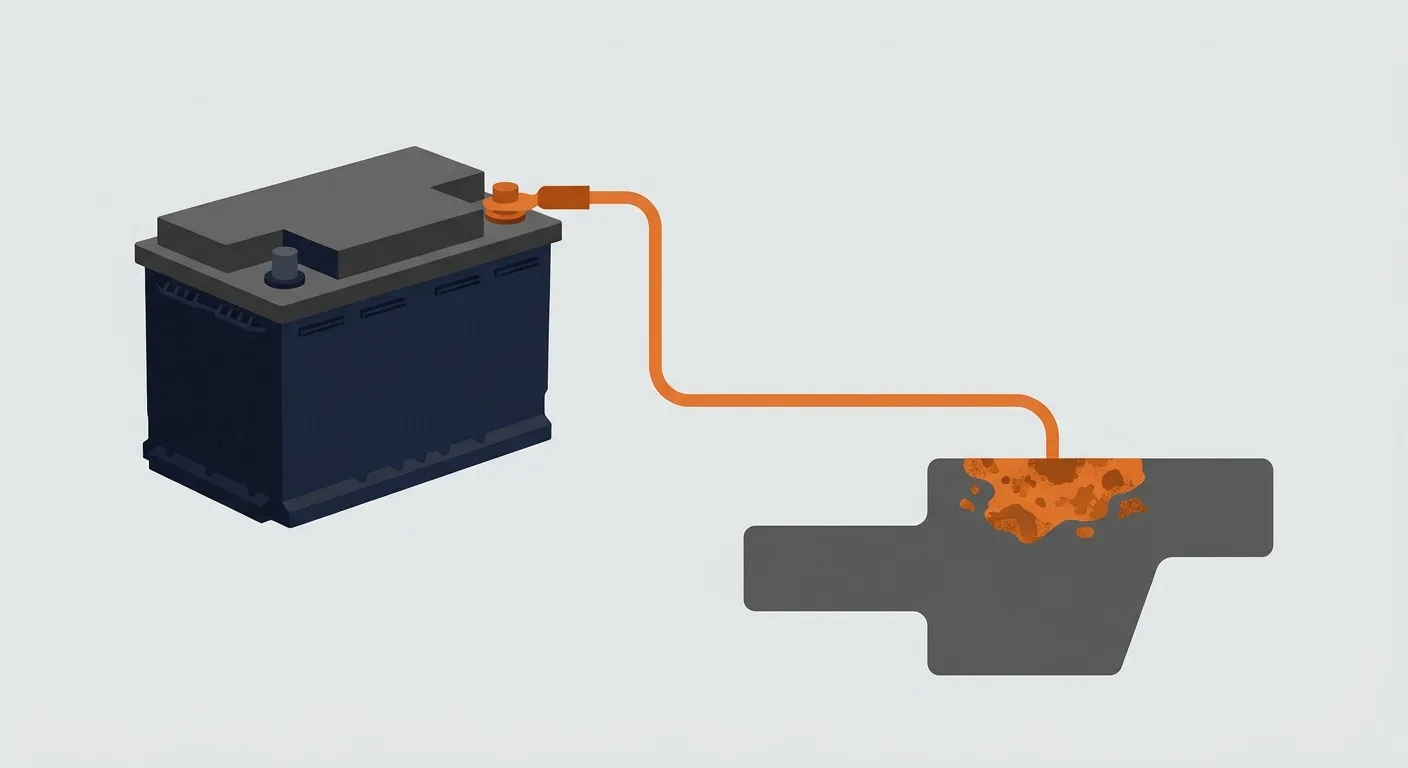
A good ground is not optional. A poor or corroded ground raises resistance, drops voltage under load and makes everything downstream misbehave. Many "mystery electrical faults" are ground faults.
Resistance is not always a fault. Every real wire and connection has some. The question is whether it is low enough for the job. A few tenths of an ohm in a high-current starter cable is a problem; the same value in a signal wire is nothing.
A bigger fuse is not a fix. The fuse is sized to protect the wiring. Fit a larger one and the wiring becomes the fuse, inside your loom. Find the fault instead.
A charged capacitor can still be dangerous after power is removed. Capacitors store energy. Discharge them safely before working near them, and never assume "switched off" means "safe".
Practice check

Try these before reading the answers.
- 12 V across 4 Ω. What current flows?
- A 24 W load on 12 V. What current does it draw?
- Two 10 Ω resistors in parallel. What is the total resistance?
- A 12 V circuit draws 2 A for 10 seconds. How much energy is used?
Answers:
- I = 12 / 4 = 3 A.
- I = 24 / 12 = 2 A.
- R_total = (10 × 10) / (10 + 10) = 100 / 20 = 5 Ω.
- P = 12 × 2 = 24 W. E = 24 × 10 = 240 J.
If those felt straightforward, you are ready for real circuits. If not, work through them once more with the formulas in front of you. There is a short self-check quiz at /electrical/quiz if you want more practice.
FAQ

What kills you, voltage or current? Current does the damage, but voltage is what drives it through your body. That is why high voltage is treated with far more caution. It is a simplification, not a licence to experiment with anything above low voltage.
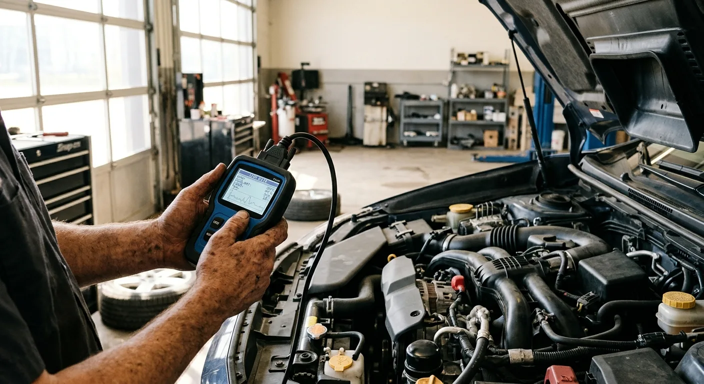
Why do I read 0 V but the device still works? A few possibilities. You may be probing the wrong points, or the meter may be on the wrong range, or you are measuring across a switch that is closed (which reads about 0 V because there is no potential difference). Check ground and probe placement first. If you are chasing a vehicle fault, the free OBD code lookup at /tools can help you narrow the circuit before you start probing.
Why does my meter read resistance when the circuit is off, but not when it is on? Resistance mode sends a small current out of the meter. Any external voltage corrupts that reading. Always measure resistance on a dead circuit.
Why do car makers use 12 V DC and not mains AC? Low-voltage DC is safer for the people handling the vehicle, works with batteries and alternators, and does not need the distribution infrastructure AC is designed for. The trade-off is higher current for the same power, which is why high-power vehicle circuits use thick cable.
Can I use a multimeter on my house wiring? Only if you are qualified and your meter is correctly rated for the environment. This article does not cover that. For a beginner, the answer is no.
One takeaway
Resistance is not an abstract nuisance. It is the number that tells you how much current a given voltage will produce, and therefore what your wiring, your fuse and your meter have to survive. Get Ohm's law and P = V × I into your head, and most electrical problems stop looking mysterious.
Put this to work on the car: check the numbers with the free battery calculator, follow the step-by-step electrical measurement guides, or start from the Electrical Hub for concepts, formulas and more diagnostics.