
A multimeter is just a voltmeter, an ohmmeter and an ammeter sharing one set of leads. That is the whole trick. What separates a useful reading from a confusing one is almost never the meter. It is whether the circuit was under load when you measured, and whether the dial and the probes were where you thought they were.
Get those two things right and a $25 meter will tell you more about a car's electrical system than a $300 one used carelessly. Get them wrong and you will chase a "good" battery that cannot crank an engine.
Meter setup in 60 seconds

Turn the dial before you touch anything. On most meters the positions you will use for car work are DC volts (marked V with a straight line above a dashed line), resistance (the omega symbol), and continuity (a diode or speaker icon). AC volts, marked with a wavy line, is for household wiring and has no place in a 12 V car diagnosis.
If your meter has fixed ranges, pick the range just above what you expect. For a car battery, the 20 V DC range is the usual choice. If it is autoranging, let it settle: the display will flicker for a second before it locks on. That lag matters later.
Plug the black lead into COM. Plug the red lead into the socket marked for volts, ohms and continuity, usually the one labelled V, ohm, mA. The 10 A socket is for current measurement only and is fused. If you measure voltage with the red lead in the current socket, you can blow that fuse or worse.
Check the leads themselves. Wiggle each plug in its socket. Look for cracked insulation and a probe tip that has gone blunt or black. A bad lead adds resistance that shows up as a phantom voltage drop, and you will spend an hour blaming a cable that was fine.
A cheap meter is usually enough for 12 V work. The accuracy you need for "is this battery charged" or "is this ground clean" is coarse. What a cheap meter may lack is a good continuity beeper and a min/max or hold function. Those are conveniences, not requirements.
Battery voltage at rest and while cranking

What it proves: whether the battery holds charge and whether it can deliver current under load. A rested battery that reads fine and collapses under the starter is a failing battery, not a charging problem.
Setting: DC volts, 20 V range or autorange.
Key state: engine and all loads off for the at-rest check. Then crank the engine for the second reading.
Probe placement: red to the battery positive post, black to the battery negative post. On the posts, not on the clamp bolts, if you can reach them.
Typical reading: a healthy, fully charged 12 V battery at rest sits around 12.6 V. Around 12.2 V suggests it is partway down. While cranking, a healthy battery usually stays above roughly 9.5 to 10 V. These are typical figures, not a spec for your car. Check your service information.
Most common mistake: measuring at rest only, then declaring the battery good. The cranking number is the one that tells the truth. If your meter has a min/max function, use it during the crank so you catch the lowest dip.
Charging voltage at idle and under load

What it proves: whether the alternator is actually charging, and whether it keeps up when you switch things on.
Setting: DC volts.
Key state: engine running at idle for the first reading. Then switch on headlights, blower on high and rear defroster for the loaded reading.
Probe placement: across the battery posts, same as before.
Typical reading: with the engine running, most 12 V systems sit somewhere around 13.5 to 14.5 V. Loaded, it may dip slightly but should stay in that neighbourhood. If it reads battery voltage with the engine running, the alternator is not charging. If it climbs well past 15 V, stop and get it checked.
Most common mistake: measuring at the alternator output stud instead of the battery. That tells you what the alternator makes, not what reaches the battery. The difference between those two numbers is the whole point of the next section.
If you want a structured walk-through of this test, the charging system check at /tools/charging-system lays out the same steps.
Voltage drop across a cable, connector or ground
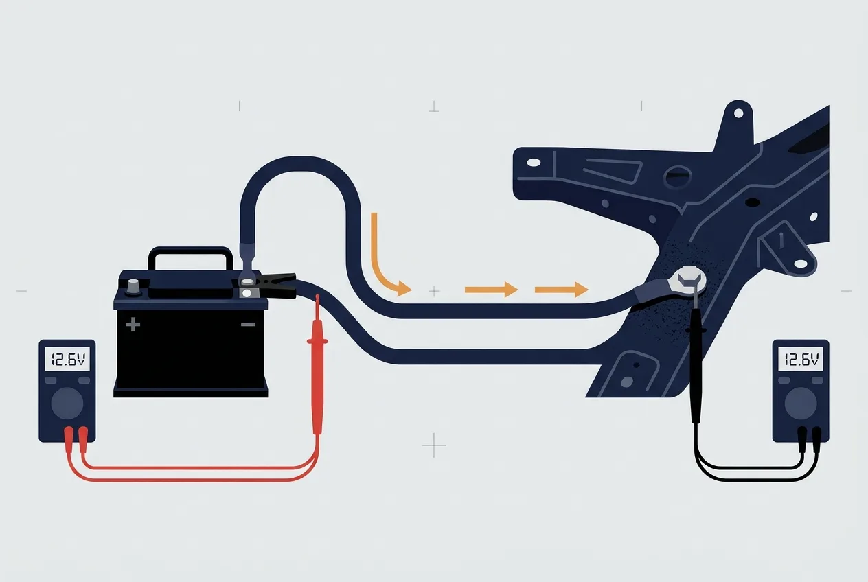
This is the measurement that finds the faults a plain voltage test misses. It is also the one most beginners get backwards.
What it proves: how much voltage is being lost in the path itself, rather than delivered to the load. A cable or connection with high resistance wastes voltage as heat.
Setting: DC volts, low range if your meter has one, because you are hunting for small numbers.
Key state: the circuit must be on and drawing current. A voltage drop test on a circuit with no current flowing proves nothing. This is why you switch on the load, or crank the engine, while you measure.
Probe placement: put one probe on each end of the thing you are testing. For a ground cable, red on the engine block end and black on the battery negative post. For a positive cable, red on the battery positive and black on the load end. You are measuring across the component, not from the component to ground.
Typical reading: a good cable or connection should show close to 0 V, often under 0.1 V. A reading of 0.5 V across a cable under load is a lot and points to a bad connection or a corroded cable. Confirm acceptable limits against your service information; do not treat these as universal.
Most common mistake: leaving the black probe on the battery negative for every test. That turns a voltage drop measurement into an ordinary voltage measurement and hides the fault. The probe has to straddle the part you suspect.
Resistance and continuity checks
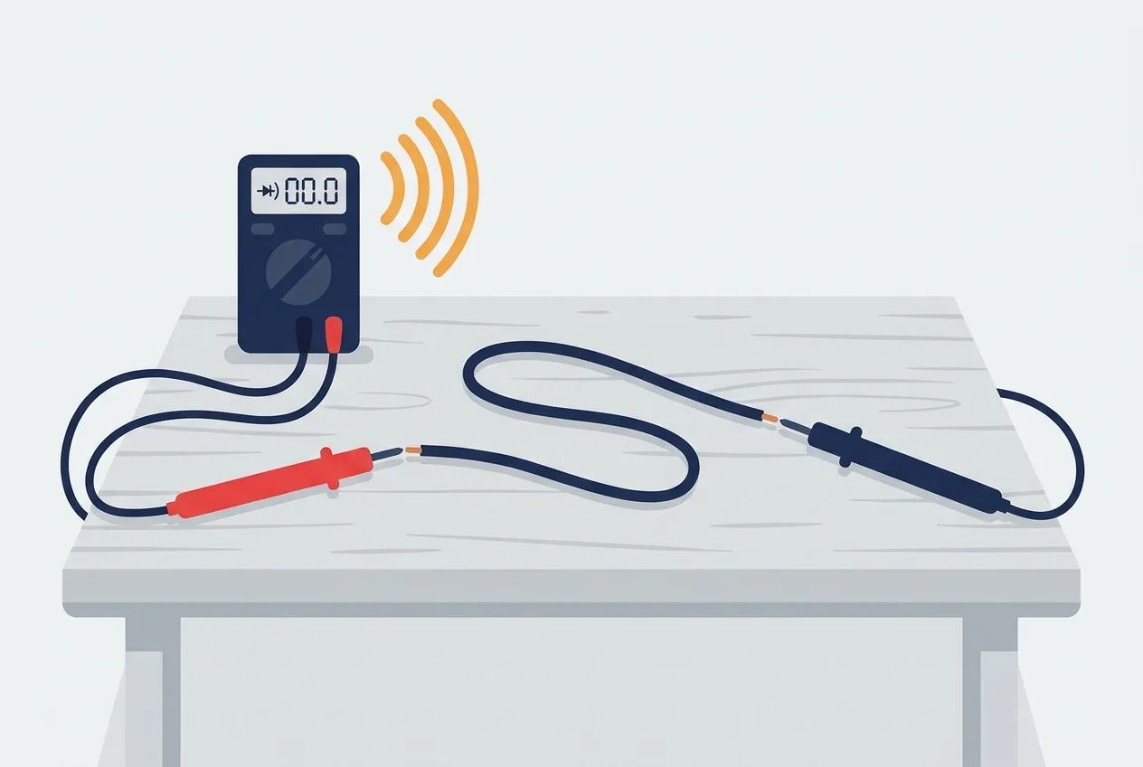
What it proves: whether a wire is broken, whether a switch closes, whether a component's internal resistance is in the right ballpark, and whether two points are actually connected.
Setting: resistance (ohms) or continuity. Continuity usually beeps when resistance is very low.
Key state: circuit off and isolated. Disconnect at least one end of the wire or unplug the component. A circuit with power in it will give you nonsense and can damage the meter.
Probe placement: one probe on each end of the wire, or across the switch terminals, with the circuit dead.
Typical reading: a good wire reads close to 0 ohms and beeps on continuity. An open circuit reads OL or shows no beep. A component's resistance depends entirely on what it is, so look it up rather than guessing.
Most common mistake: testing continuity on a live circuit. Never do it. The meter injects its own small voltage to make the measurement, and a live circuit fights it. Isolate first, every time. The electrical measurement guides at /electrical/measurements go deeper on this.
Current draw with a clamp meter vs an inline meter
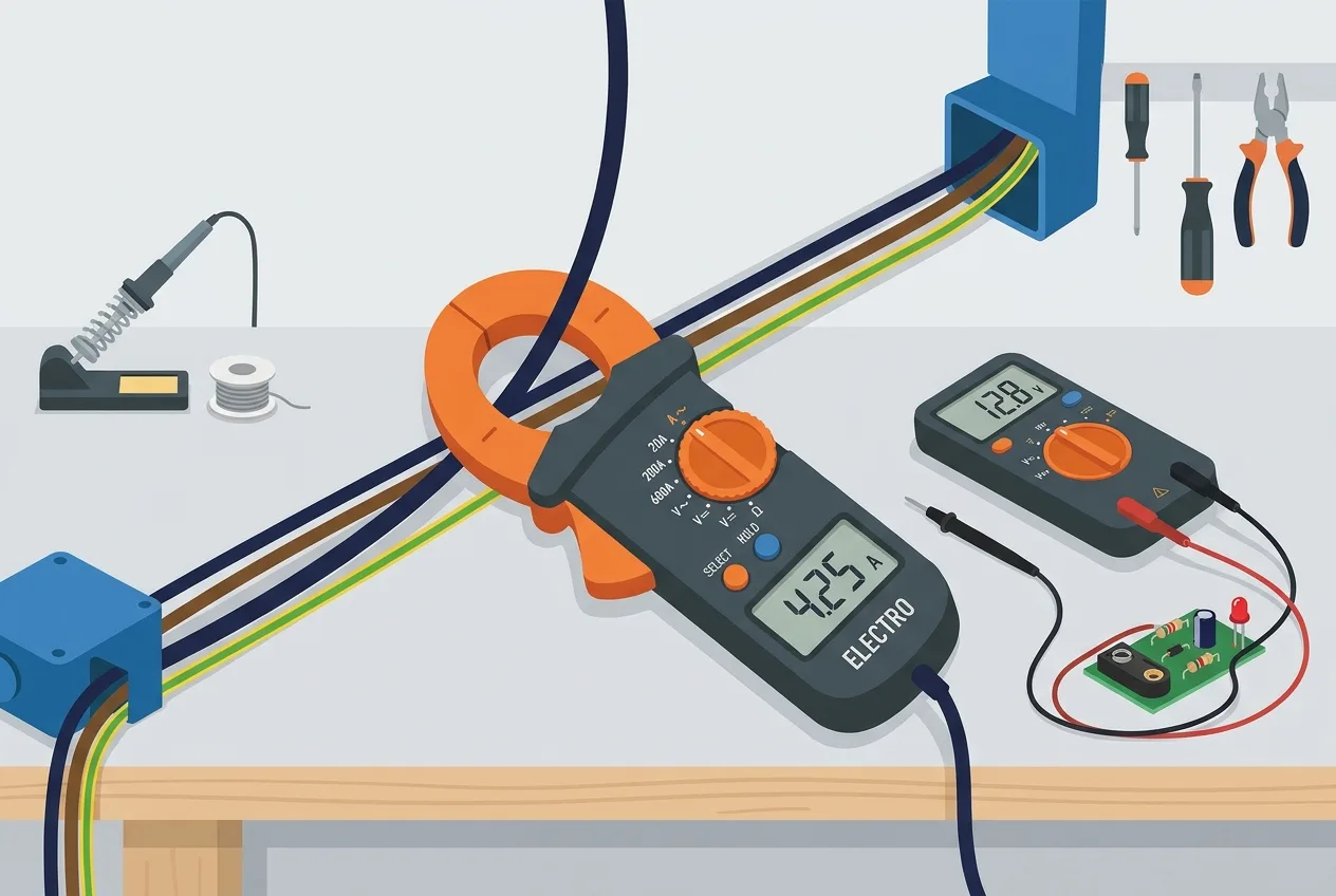
What it proves: how much current a circuit is pulling. This is how you find a parasitic drain that flattens a battery overnight.
Clamp meter: clip the jaws around a single wire, set the dial to DC amps, and read. No need to break the circuit. Many cheap clamp meters only read AC amps, so check yours before you trust a DC reading. The jaws must close fully around one wire only.
Inline meter: set to DC amps, put the red lead in the 10 A socket, and connect the meter in series with the circuit. That means you break the circuit and the current flows through the meter. Never connect an ammeter in parallel with a battery; that is a dead short through the fuse.
Key state: for a drain test, everything off and the car asleep. Some cars take several minutes to go to sleep, so give it time.
Typical reading: a small drain, tens of milliamps, is often normal. A drain of a few hundred milliamps or more will kill a battery over a few days. Check your service information for what is acceptable.
Most common mistake: using the wrong socket on an inline meter, or forgetting that most inline meters are only rated for 10 A and for short periods. For anything bigger, use a clamp.
How to read the numbers
Here is a rough guide to voltage drop, based on a circuit under load. Treat it as a starting point, not a rule.
| Reading across a cable or connection | Likely cause |
|---|---|
| Under 0.1 V | Normal. Move on. |
| 0.1 to 0.3 V | Mild resistance. Clean and retighten the connection. |
| 0.3 to 0.5 V | Noticeable loss. Suspect a corroded terminal or a tired cable. |
| Over 0.5 V | Significant fault. The cable, connector or ground is the problem, not the component. |
A large drop across a ground cable points at the ground. A large drop across a positive cable points at the cable or its terminals. If the drop is small everywhere but the component still does not work, the component is the suspect.
Probe placement mistakes

Back-probing damage. Pushing a probe through the insulation of a wire, or into the back of a sealed connector, can break strands or open up the seal and let water in. Use the proper back-probe pins where you can, and avoid piercing insulation on anything you care about.
Measuring on the wrong side of a connector. If you probe the supply side of a connector and get 12 V, that only tells you the supply is good. It says nothing about what the load sees. Probe the load side, under load.
Using chassis as a universal ground. The chassis is not a perfect conductor. A rusty or loose ground point changes the reading. When you test a ground, test across it, not from it to somewhere convenient.
Meter lead resistance. Cheap leads have their own resistance, usually small but not zero. If you are measuring very low resistance, touch the two probes together first and note the reading. Some meters have a relative or zero function to subtract it.
Autorange lag. On an autoranging meter, the display takes a moment to settle. If you glance and see a number, wait a beat and look again. Chasing a flicker that was just the meter changing range wastes time.
Practice checklist

Run these on your own car this weekend. They take under an hour and you will learn more than reading ten articles.
- Battery at rest. Engine off, everything off, measure across the posts. Note the number.
- Cranking dip. Use min/max if you have it, crank the engine, and read the lowest voltage.
- Charging voltage. Engine running, measure across the posts. Then switch on the lights and blower and measure again.
- Ground voltage drop. With the engine cranking or a big load on, measure from the engine block to the battery negative. Note the reading.
- Continuity on a known-good wire. Pick a wire you know is intact, isolate it, and confirm your meter beeps. Then try a wire you know is broken.
- Parasitic drain, if you are curious. Clamp meter around the negative cable with everything off and the car asleep. Note the milliamps.
If a number surprises you, cross-check it against a second meter or a second test point before you act. One reading is a data point, not a diagnosis. For related diagnostic procedures, the electrical diagnostics guides at /electrical/diagnostics are worth a read, and the free calculators at /tools can help you sanity-check expected values.
FAQ
Which multimeter should I buy? For 12 V car work, any decent meter with DC volts, resistance, continuity and a beeper will do. Look for one with a 10 A fused current socket and, if you can, a min/max function. You do not need a lab-grade meter to find a bad ground.
Can I use continuity on a live circuit? No. Isolate the circuit first. A live circuit will give you false readings and can damage the meter. This is not a rule of thumb; it is how the measurement works.
Why does my reading jump around? A few reasons. Autorange lag, a loose probe, a bad lead, or a circuit that is actually intermittent. Wiggle the probes and watch the display. If it settles, it was the connection. If it does not, the circuit has a fault.
Is 0.5 V drop a lot? Yes, on a 12 V system under load, half a volt across a single cable or connection is significant. It points to resistance in that path. Check your service information for what is acceptable, but treat 0.5 V as a reason to investigate.
Do I need a clamp meter? For current measurement, it is far safer and easier than an inline meter. If you plan to hunt parasitic drains, a clamp meter that reads DC amps is a good investment. Check that it reads DC before you buy.
The takeaway
A multimeter does not diagnose anything. It reports a number, and you decide what it means based on where the probes were and whether the circuit was under load. Set the dial correctly, put the probes across the right thing, and make sure current is flowing. Do that, and the meter becomes the most useful tool in your box.