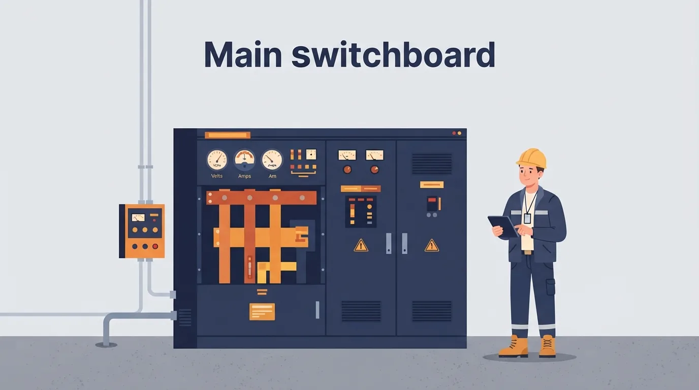
Power factor is one of those numbers that shows up on a bill, a drive display or a panel meter, and plenty of people nod at it without being sure what it is telling them. In an industrial installation it sits right where the supply meets the load: the main switchboard, the distribution boards, the motor control centre and every cable and starter downstream of them. Read it properly and you can tell whether a plant is paying for current it never uses, why a transformer or generator feels "full" before it is actually loaded, and why a cable runs warmer than the amps suggest.
This guide is for the maintenance technician, industrial electrician or engineer who needs the system-level picture rather than a derivation. The one decision it should help you make is simple: when you see a poor power factor or a motor behaving badly, do you reach for correction equipment, or do you go looking for a fault first?
A word before anything else. Everything here is about understanding and diagnosis. Live work, isolation, testing and final verification belong to qualified, authorised personnel working under the site's safety rules, permit-to-work system and electrical safety programme. No article replaces those.
What power factor actually means
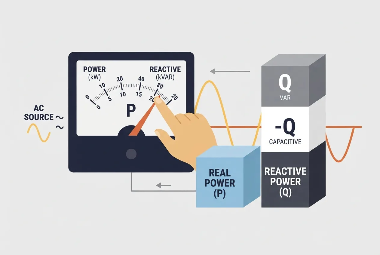
In plain terms, power factor is the ratio of real power (watts) to apparent power (volt-amperes) in an AC circuit. Real power does the work. Apparent power is what the supply has to deliver to make that work happen. The gap between them is reactive power, which shuttles back and forth and does no useful work but still loads the cables, transformers and generators.
The symbol cos φ is the cosine of the phase angle between voltage and current. If voltage and current rise and fall together, the angle is zero and the power factor is 1. If current lags voltage, which is what motors and transformers do, the power factor is less than 1 and the load is inductive. A number close to 1 is good. A number well below it means the supply is working harder than the useful output justifies.
For a three-phase system the relationship is:
Real power (W) = √3 × line voltage × line current × cos φ
That one line is worth keeping in your head. It explains why a motor with a poor power factor draws more current for the same mechanical output, and why that current shows up as heat in cables and losses in transformers.
Three-phase fundamentals
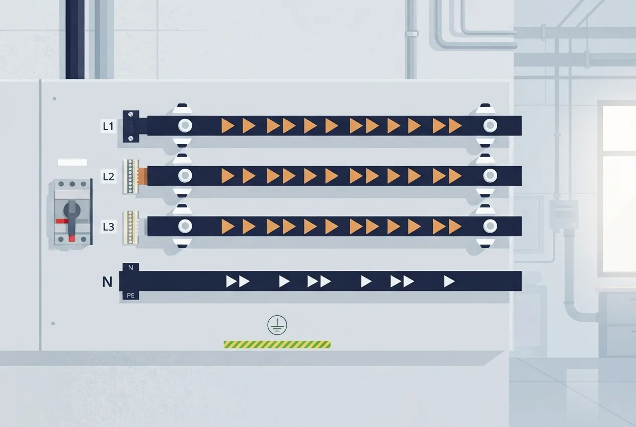
Most industrial supply is three-phase because it delivers constant power and lets simple, rugged motors run without special starting gear. Three line conductors carry currents that are equal in magnitude and separated in phase. A neutral may be present for single-phase loads and for the star point of certain systems.
You will meet two voltages. Phase-to-phase voltage is measured between any two line conductors. Phase-to-neutral voltage is measured between one line and neutral. In a common European arrangement this is often quoted as a 400 V / 230 V system, where 400 V is the line-to-line value and 230 V the line-to-neutral value, related by √3. Treat that as an illustration only. The actual value on your site must be verified on the equipment nameplate and with a proven tester before you rely on it for anything.
A balanced load draws equal current in all three lines, and the neutral current in a healthy balanced system is close to zero. Unbalance is a fault symptom, not a normal condition.
Phase sequence is the order in which the three phases reach their peak. Three-phase motors rotate because the stator windings produce a rotating magnetic field, and the direction of that field follows the phase sequence. Swap any two line conductors and the motor runs backwards. That is the whole secret behind the FAQ later.
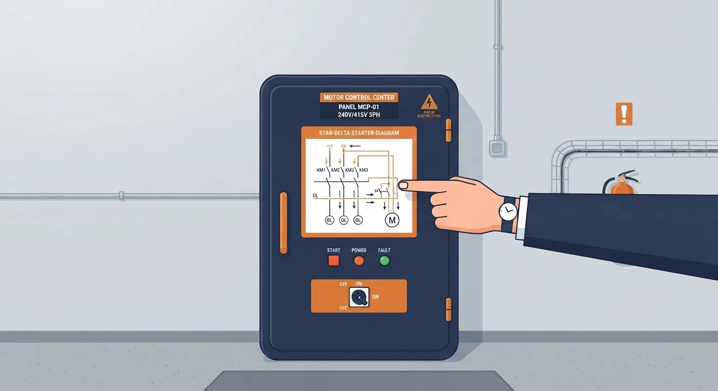
Star and delta connections decide how the motor windings see the supply. In star, each winding gets phase-to-neutral voltage. In delta, each winding gets full phase-to-phase voltage. A motor may be designed to start in star and run in delta, or to run only in one configuration. The nameplate and terminal-box diagram are the authority, and guessing here destroys motors.
Motor starters and protection
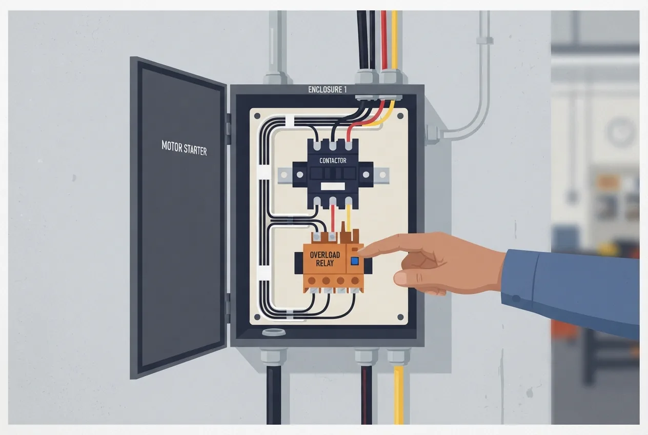
A motor starter is a coordination exercise. Each device has a job, and the job is not the same for all of them.
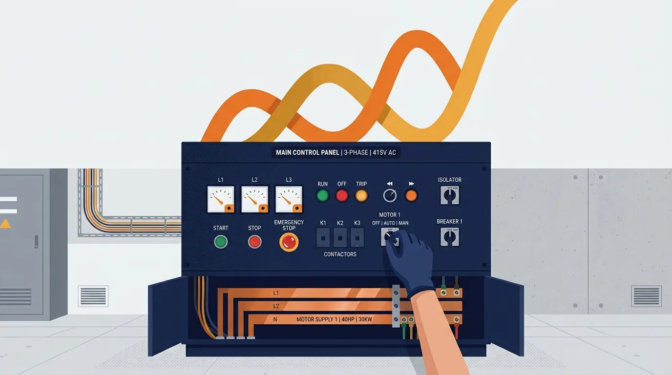
A contactor switches the motor on and off under normal load. It is a control device, not a protective one. An overload relay protects the motor from sustained overcurrent and from the heating that follows a lost phase or a mechanical jam. A fuse or circuit breaker protects the cable and the installation from short-circuit current. The protective earth and the enclosure protect people. Coordination means these devices are selected so that the one nearest the fault operates first, and so that a short circuit does not destroy the contactor or the overload.
When a motor will not start, work through it in a fixed order rather than jumping around:
- Supply. Is voltage present at the incoming terminals, all phases, as confirmed with a proven tester under the site's isolation rules?
- Control circuit. Is the control supply healthy, and are the control fuses intact?
- Emergency stop and interlocks. Is an E-stop latched, a guard switch open, a level or pressure interlock holding the start out? Never bypass an interlock to "test" a motor.
- Contactor coil. Is the coil being energised, and does the contactor pull in cleanly?
- Overload. Has the overload relay tripped, and if so why? A tripped overload is a message.
- Motor and load. Is the motor free to turn, is the driven equipment jammed, is the winding healthy?
That sequence saves time because it moves from the cheapest checks to the most expensive ones.
Variable frequency drives
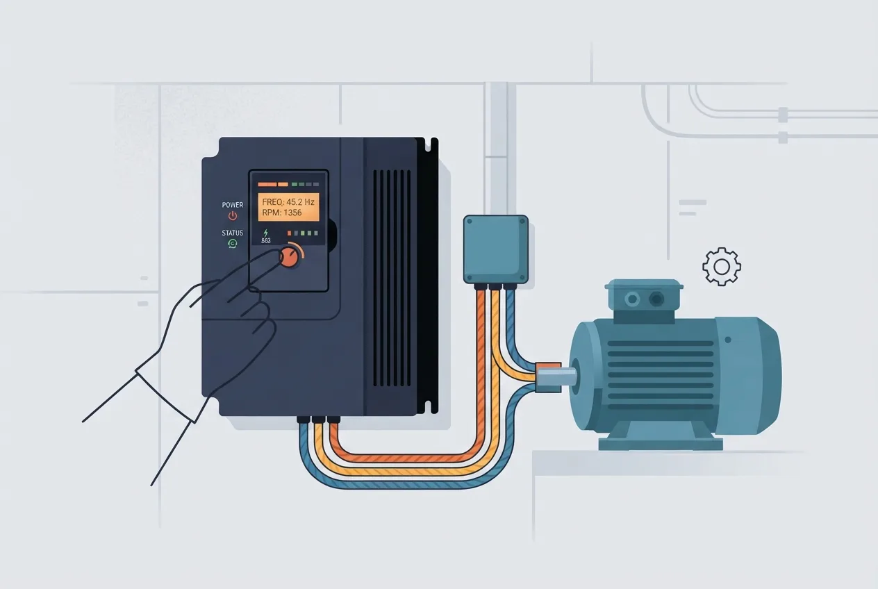
A VFD takes the fixed-frequency supply, rectifies it to a DC link and then synthesises an output with adjustable frequency and voltage. That is what lets it control motor speed and torque rather than just switching the motor on and off. The motor still sees a three-phase supply, but the waveform is not a clean sine wave, which is why cable type, cable length and earthing matter so much. Long motor cables and poor screening cause reflected voltages, bearing currents and nuisance trips.
Drive faults fall into a few broad families: overcurrent, overvoltage (often during deceleration when the motor regenerates), undervoltage (supply dips or a weak incoming supply), overheating (cooling fans, filters, ambient temperature), earth fault (insulation breakdown or a damaged cable) and communication faults (fieldbus wiring, termination, addressing).
The specific parameter numbers, wiring terminals and fault codes differ between manufacturers and model families. Read the manufacturer documentation. Do not copy settings from a drive on another machine because it "looks the same". If you want background on how the motor side of the system behaves, the mechanical encyclopedia is a useful reference for the components downstream of the drive.
Earthing and bonding
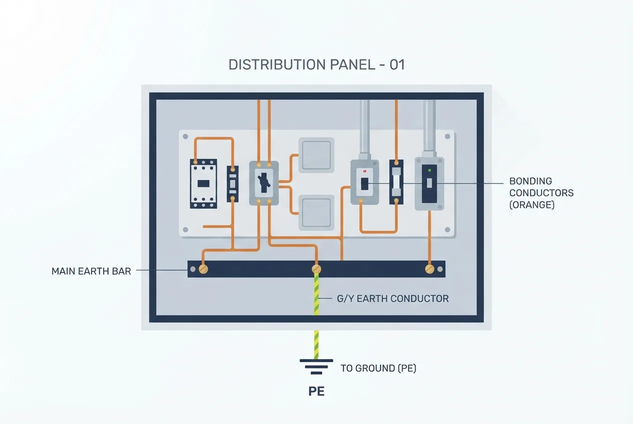
Protective earthing gives fault current a low-impedance path back to the source so that protection operates quickly and touch voltages stay low. Equipotential bonding ties together exposed conductive parts and extraneous conductive parts so that no dangerous potential difference can develop between them.
A lost earth is a safety problem, not an inconvenience. Without a reliable fault path, a phase-to-frame fault may not trip anything, and the enclosure can sit at a dangerous potential waiting for someone to touch it. Earth-resistance limits are defined by the applicable standard and the site procedure, and they are not something to guess at. Measure and record what the site requires.
Panel diagnostics
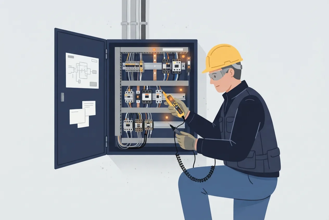
Diagnostics should be orderly. The order is what keeps you safe and stops you chasing ghosts.
Identify the panel, the isolation point and the upstream supply. Read the drawings and labels before you touch anything. Confirm absence of voltage with a proven tester, and prove the tester itself before and after. Then inspect: look for heat discolouration, loose terminations, burnt contacts, swollen capacitors and signs of moisture or vermin. Check the control supply, then the interlocks, then test the circuit.
Thermal imaging and insulation resistance testing are qualified tasks with their own procedures. Thermal imaging finds hot joints under load that look fine when dead. Insulation testing tells you about winding and cable health, but only when done correctly and with the right instrument for the circuit. The step-by-step guides section has related walkthroughs if you want to see how these checks are sequenced in practice.
Safety first: LOTO and arc flash
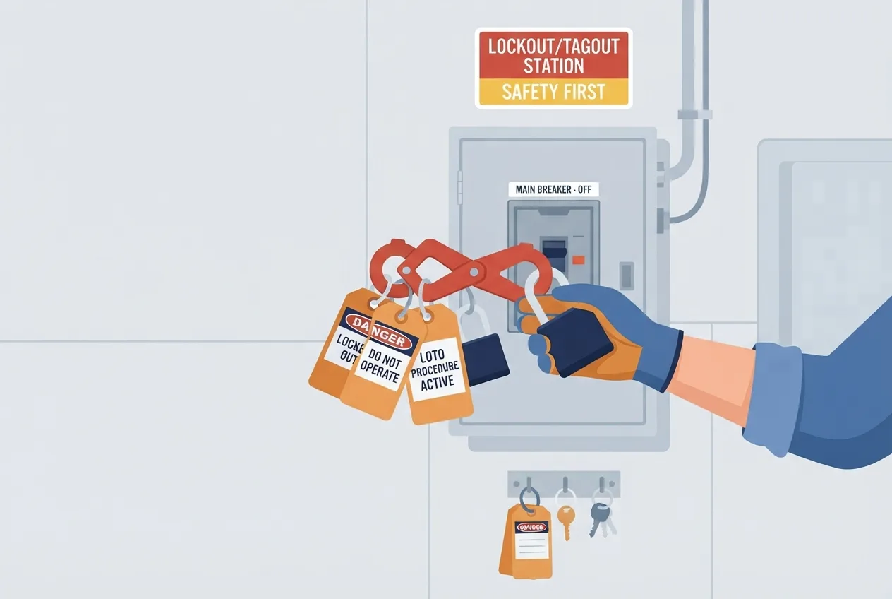
Lockout/tagout is not paperwork. It is the procedure that keeps a machine from being energised while someone is working on it. The steps are consistent: identify all energy sources, isolate them, lock and tag, prove dead with a proven tester, discharge stored energy in capacitors, springs and drives, and verify the isolation before starting work.
PPE and arc-flash boundaries come from the site's electrical safety programme and the applicable standard, not from a rule of thumb. The boundaries depend on the equipment, the available fault current and the protection settings. If you do not know the boundary, find out before you open the panel.
Never work alone on live equipment. Never bypass an interlock. This section is not a substitute for the site's permit-to-work and electrical safety programme; it is a reminder of why that programme exists.
Preventive maintenance
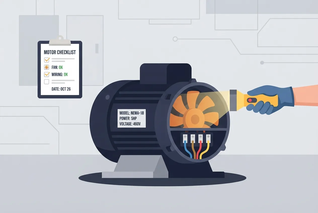
Most failures announce themselves before they happen. Periodic checks on terminations, cooling fans, filters, contactor wear and cable condition catch the obvious ones. Drive logs are underrated: they record the sequence of events around a trip, which is often more useful than the trip itself. Keep documentation current and keep a disciplined spare-parts list so that a replacement is the correct one and not "close enough".
And a nuisance trip is information, not something to defeat. If an overload trips at the same point every week, something is wrong. Bypassing the protection just moves the failure to somewhere more expensive.
A short diagnostic case
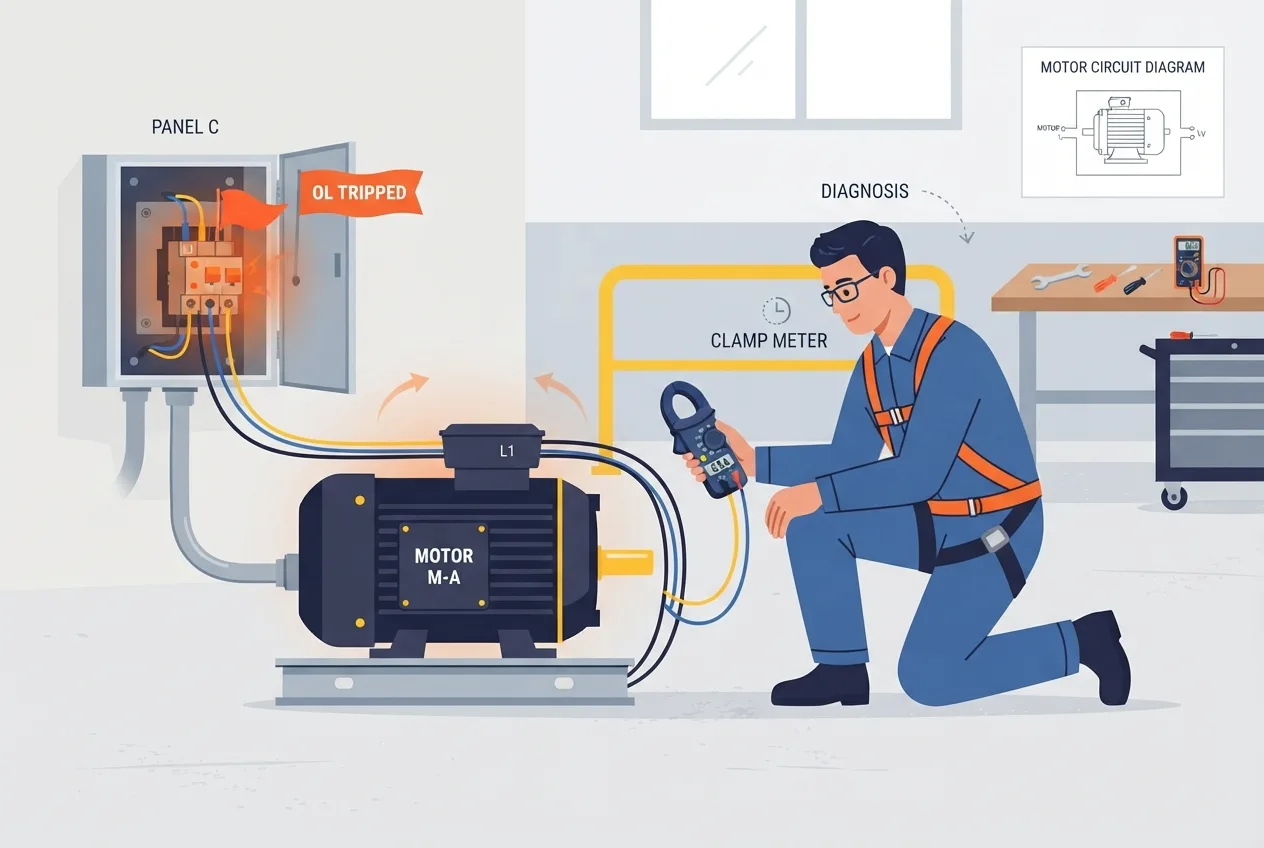
A motor trips its overload after running for about ten minutes. It starts fine, runs fine, then trips. That pattern narrows the field.
The hypotheses worth testing are mechanical load (a bearing, a jammed conveyor, a pump running off its curve), voltage imbalance (one phase low, causing current imbalance and heating), insulation degradation, poor ventilation (blocked cooling ducts, a failed fan, a hot location) and an overload setting that is simply wrong for the motor.
A qualified technician would measure line currents on all three phases and compare them, check the supply voltage on all three phases, inspect the motor cooling and ambient conditions, and compare the overload setting against the motor nameplate. Insulation testing and thermal imaging would follow if the basic measurements did not explain it. If the fault turns out to be mechanical, the free car tools and general diagnostic reference material are useful for thinking about how load and current interact, even though this case is industrial rather than automotive.
FAQ
Why does a three-phase motor run backwards? Because two of the line conductors have been swapped somewhere between the supply and the motor. The rotating field follows phase sequence, so reversing the sequence reverses rotation. Check the supply, the starter and the motor terminal box.
Can I use a VFD on any motor? Not automatically. Standard induction motors often work, but factors like insulation class, cooling at low speed, cable length and bearing currents matter. Verify against the motor nameplate and the drive manufacturer's guidance.
Why does the drive trip on an earth fault? Usually a breakdown in insulation in the motor or cable, or moisture in a terminal box. The drive detects the imbalance and trips to protect itself and the installation. Find the fault; do not reset it repeatedly.
Why does the power factor matter if the motor still runs? Because poor power factor means higher current for the same real power, which means more losses, more heat and less capacity from the supply. Correction equipment or better motor selection can reduce that.
One takeaway
Power factor explained in a sentence: it tells you how much of the current the supply delivers is actually doing useful work. Learn to read it alongside the current and voltage measurements, and treat every trip and every poor reading as a clue rather than an obstacle. Verify every value against the nameplate, the manufacturer documentation and the site's standards. That habit will keep you, your equipment and your plant out of trouble.