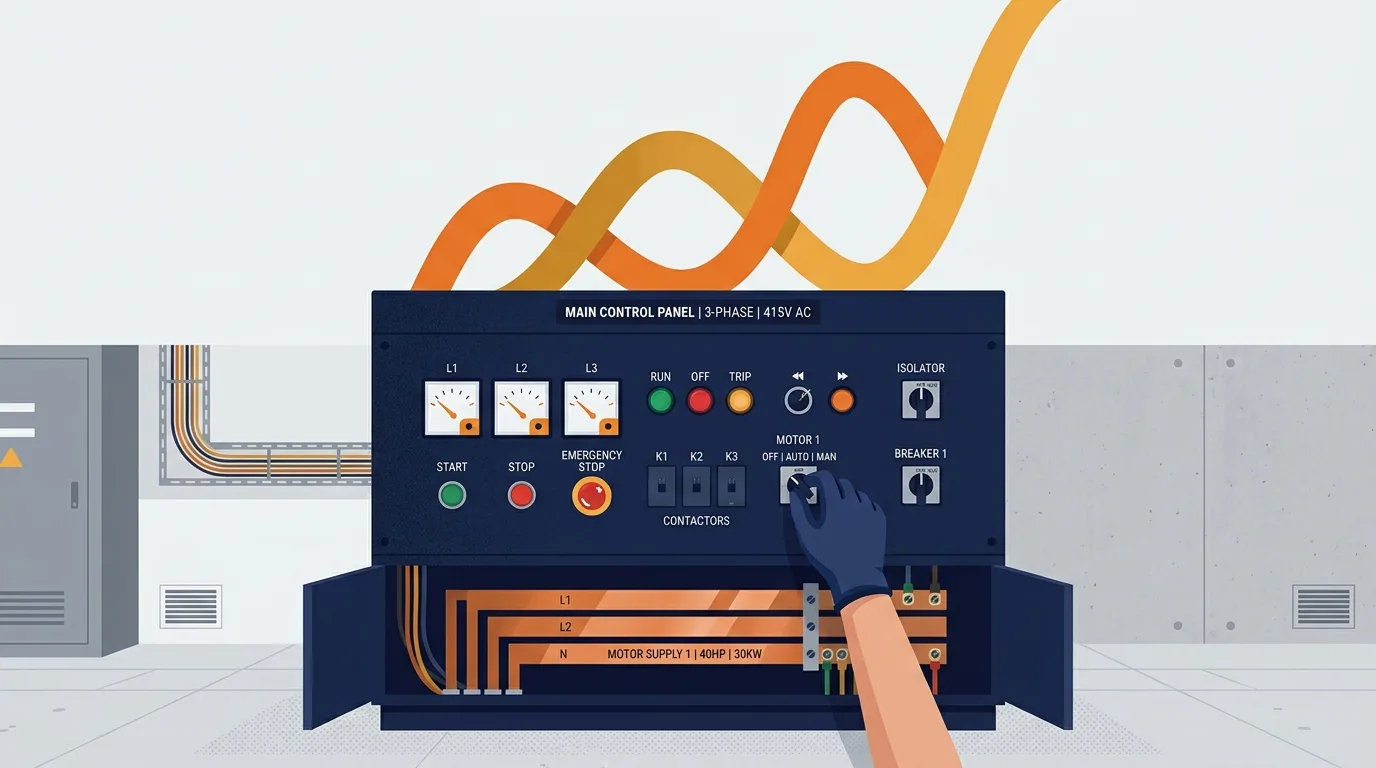
If you maintain industrial equipment, three-phase power is the system you live inside every shift. This article covers the part of the installation between the main distribution board and the motor terminal box: voltages, currents, power, starters, drives, earthing, and the checks that actually find faults. It won't make you competent to work live, and it isn't meant to. Switching, isolation, live work and final verification belong to qualified, authorised personnel working under the site's electrical safety rules and permit system. What it will do is help you make one practical call: when a three-phase motor misbehaves, is the problem in the supply, the control circuit, the protection, or the driven load?
Three-phase fundamentals
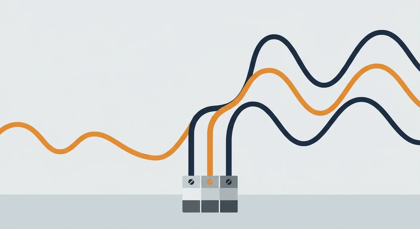
A single-phase supply gives you one alternating voltage that rises and falls in a sine wave. Three-phase gives you three of those waves, each offset from the next by one third of a cycle. In a 50 Hz system that's 120 electrical degrees apart. The offset is the whole trick: while one phase is near zero, the other two are still pushing, so the total power delivered to a balanced load never drops to zero. That's why three-phase motors run smoothly instead of pulsing, and why three-phase cable carries more power for the same copper.
First, the quantities and units, because loose language causes real mistakes on site:
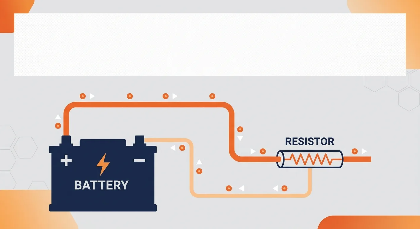
- Voltage (V) is the electrical pressure, measured in volts. It's a difference between two points, so you always have to say which two.
- Current (A) is the rate of charge flow, measured in amperes.
- Power (W) is the rate of energy transfer, measured in watts. In motor work you'll usually see kilowatts (kW), where 1 kW = 1000 W.
- Power factor (PF) is a number between 0 and 1 that accounts for current that does no useful work in an inductive load like a motor. It has no unit.
The conductors matter too. The three line or phase conductors carry the load current. The neutral carries current only when the load is unbalanced or when single-phase equipment is connected phase-to-neutral. The protective earth normally carries no current at all, and that's exactly the point: it sits there waiting for a fault.
Line voltage and phase voltage
Here's the relationship that trips people up. In a star-connected (wye) system, the voltage between any two line conductors is the line voltage, and the voltage between one line conductor and neutral is the phase voltage. They're related by the square root of three, about 1.732:
V_line = V_phase × √3
Take a common European distribution arrangement as an illustrative example only: a 400 V line-to-line system. The phase-to-neutral voltage would be:
V_phase = 400 V ÷ 1.732 = 231 V, rounded to about 230 V
That's where the familiar 400/230 V designation comes from. In North America you'll more often meet 480/277 V or 208/120 V arrangements. Do not assume any of these applies to your site. Measure it, or read it from the nameplate and the drawings, before you touch anything. The numbers above are a teaching example, not a site value.
Balanced loads, and the measurement that matters
A balanced load draws equal current on all three lines, with the currents offset by the same 120 degrees. Under that condition the neutral current is theoretically zero, because the three return paths cancel. That's why some three-phase motor circuits have no neutral at all.
An illustrative worked example, clearly labelled as an example and not a specification:
Suppose a balanced three-phase load draws 10 A per line on a 400 V system with a power factor of 0.85. The total real power is:
P = √3 × V_line × I_line × PF P = 1.732 × 400 V × 10 A × 0.85 P = 1.732 × 400 × 10 × 0.85 = 5889 W, so about 5.9 kW
Now the same load, but with the current uneven: 10 A, 10 A and 14 A. The average is about 11.3 A, but you should not simply plug the average into the formula and trust the answer. Unbalanced current means the load isn't behaving as designed, and the cause matters more than the arithmetic. Clamp each line separately and compare. If one line sits persistently higher, you're looking at a single-phase load on a three-phase circuit, a failing winding, a loose termination, or a supply-side problem. That comparison is one of the quickest diagnostic habits you can build.
Power factor itself is worth understanding because it changes your current. A motor at 0.85 PF draws more current for the same real power than one at 0.92. Current, not power, heats cables and trips breakers. If you want the formulas laid out cleanly, the electrical formulas reference is a good desk reference, and the electrical concepts library covers the underlying theory if you want to go deeper.
Phase sequence and why motors spin
Three-phase motors rotate because the three phase currents produce a rotating magnetic field. Swap any two of the three line conductors and the field rotates the other way, so the motor runs backwards. That's it. No rewiring of the motor, no parameter change: just two conductors swapped. On a pump or a conveyor, getting this wrong is expensive, so phase sequence is checked with a sequence meter before first run, not discovered afterwards.
Star and delta, briefly
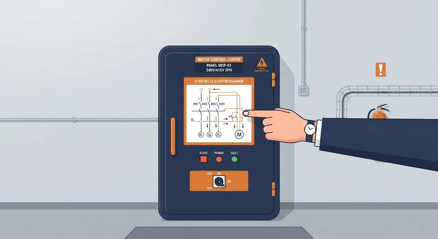
A motor's terminal box usually gives you both options. In star, one end of each winding is joined at a common point, and the winding sees the phase voltage. In delta, the windings are connected end to end in a loop, and each winding sees the full line voltage. Star-delta starting uses exactly this: start in star so each winding gets less voltage and the motor draws less starting current, then switch to delta for full running torque. The nameplate tells you which connection is valid for which supply voltage. Follow it.
Motor starters and protection
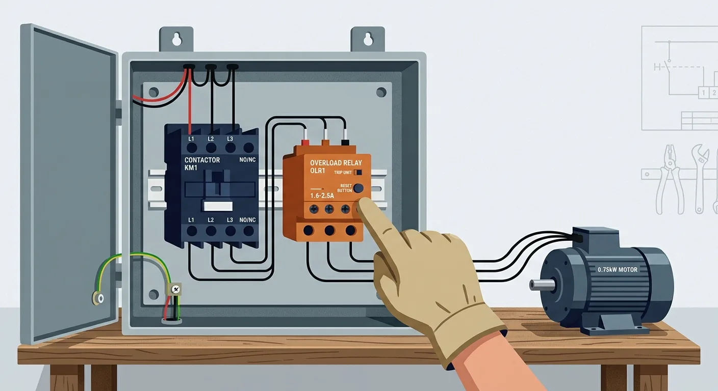
Every device in a starter has one job, and knowing which job belongs to which device stops you from "fixing" the wrong thing.
- The contactor switches the motor. It's a switching device, not a protective one. Do not treat it as protection.
- The overload relay protects the motor from sustained overcurrent. It's set to the motor's full-load current from the nameplate, and it's deliberately slow so it rides through normal starting current.
- Fuses and circuit breakers protect the cable and the installation from short-circuit current. A breaker sized for the cable will not necessarily protect the motor, and an overload relay will not clear a short circuit.
- The protective earth and the bonding system protect people. Nothing else does that job.
Coordination means these devices are selected so that the one nearest the fault operates first, and so that the combination can safely withstand a fault without the contactor welding or the enclosure failing. That coordination is a design decision backed by the manufacturer's tables. Don't substitute a device "because it fits the DIN rail."
A motor won't start: check in this order
Work through it in sequence. Skipping ahead wastes time and can send you chasing a contactor when the fault is an open emergency stop.
- Supply. Is voltage present at the incoming terminals, all three lines, with the isolator closed? Measure phase-to-phase and, if relevant, phase-to-neutral.
- Control circuit. Is the control supply healthy? Control transformers and control fuses fail more often than people expect.
- Emergency stop and interlocks. Every E-stop, guard switch, level switch and remote interlock is in series in the control circuit. One open contact stops everything, and it's usually the fastest thing to rule out.
- Contactor coil. Is the coil getting its command voltage? A coil that hums but doesn't pull in, or a coil with an open circuit, tells you the control circuit is fine and the contactor isn't.
- Overload. Has the relay tripped or is it set wrongly? Reset it only after you understand why it operated.
- Motor and load. Is the motor free to turn? Can you rotate the shaft by hand with the power off and locked out? Is the driven equipment jammed?
That order moves from the supply toward the load, which is also the direction fault current flows. On a related note, the same "supply first, then control, then load" logic applies to vehicle electrical faults, and the electrical diagnostics guides walk through it in a different context.
Variable frequency drives
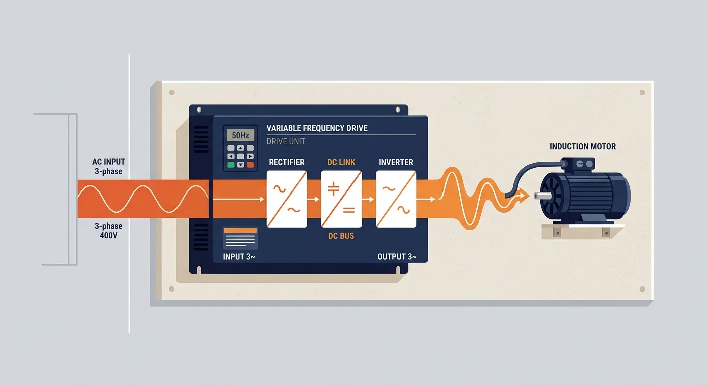
A VFD takes the incoming fixed-frequency three-phase supply, rectifies it to a DC link, and then switches it back into a variable-frequency, variable-voltage output. That's the plain-language version. What it changes is motor speed, and because torque and speed together set power, it changes the current the motor draws too. A fan or pump on a drive often runs at part speed most of the time, drawing far less power than it would at full speed.
The practical consequences for you:
- Cable type and length matter. The drive's fast switching produces high-frequency effects on the motor cable. The manufacturer specifies screened cable, earthing arrangements and a maximum cable length for a reason. Exceed the length or use the wrong cable and you get nuisance trips, bearing currents or interference with other equipment.
- Earthing matters more, not less. The screen and the protective earth are part of the drive's EMC design. Disconnecting an earth to "stop the noise" creates a hazard.
- Fault codes are categories, not verdicts. Overcurrent points at the motor, the cable or the load. Overvoltage and undervoltage point at the supply or at deceleration behaviour. Overheating points at the drive's cooling or the ambient temperature. Earth fault points at insulation or at a cable problem. Communication faults point at the network wiring or addressing. Each category narrows the search; it doesn't finish it.
Parameter settings, terminal assignments and fault-code meanings come from the manufacturer's documentation for that exact model. Read it. Guessing at parameters on a drive you don't know is how production lines go down.
Earthing and bonding
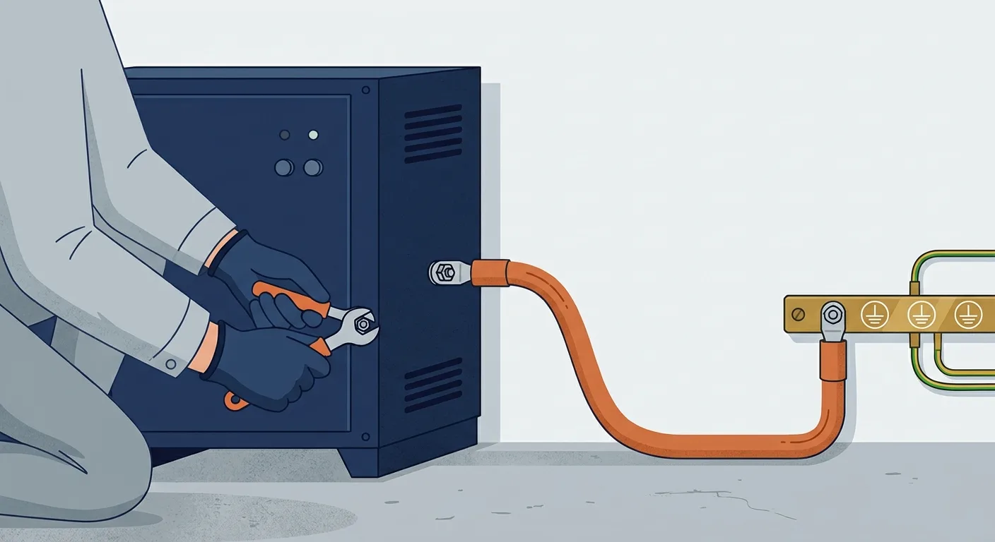
Protective earthing gives fault current a low-impedance path back to the source so that the protective device operates quickly. If a live conductor touches a metal enclosure and the earth path is intact, the resulting fault current trips the breaker or blows the fuse. If the earth path is missing or high-resistance, the enclosure sits at a dangerous potential and waits for someone to touch it. That's the whole safety argument, and it's why a lost earth is a serious defect, not a minor documentation issue.
Equipotential bonding ties exposed metalwork together so that different parts of an installation can't sit at substantially different potentials during a fault. It's what stops a voltage difference appearing across your body between two pieces of equipment you're touching at the same time.
Earth resistance limits, test methods and intervals are defined by the applicable standard and your site's procedures. They are not a number to be guessed at or copied from a forum. Verify against the standard and the site documentation.
Panel diagnostics
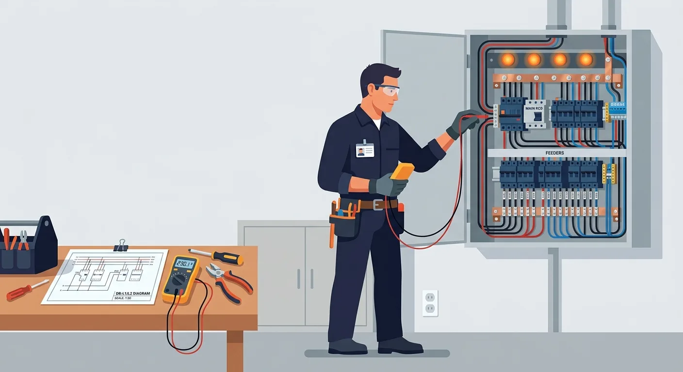
When you open a panel, have a method. Improvising inside a live enclosure is how people get hurt.
- Identify the panel and the isolation point. Know what it feeds and where the upstream isolator is before you need it.
- Read the drawings and labels. If the drawing doesn't match the panel, stop and find out why. Someone has changed something.
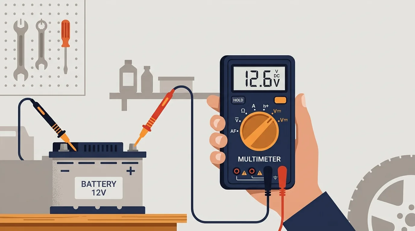
- Confirm absence of voltage with a proven tester. Prove the tester on a known live source before and after the test. A tester that only beeps is not proof.
- Inspect for heat, loose terminations and burnt contacts. Discolouration, hardened insulation and the smell of hot phenolic are all evidence. Look before you measure.
- Check the control supply. Then check interlocks, then test the circuit.
Two tasks belong to qualified people with the right equipment and procedures: thermal imaging under load, which finds loose joints and overloaded conductors before they fail, and insulation resistance testing, which finds degrading winding and cable insulation. Both are genuinely useful and both are easy to do badly. The electrical measurement guides cover meter technique and safe measurement practice in more detail.
Safety first: LOTO and arc flash
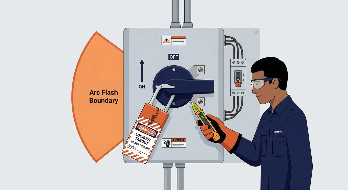
Lockout/tagout follows a fixed sequence. Identify all energy sources, including control supplies and any stored energy in capacitors, springs or elevated loads. Isolate. Lock and tag. Prove dead with a tested, proven instrument. Discharge or restrain stored energy. Only then work.
Arc flash is the reason a panel you've opened a hundred times still deserves respect. An arc fault can release enormous energy in a fraction of a second, and the available energy depends on the supply and the protective device settings at your site. Arc-flash boundaries and the required PPE come from a site-specific assessment, not from a general article. Never work alone on live equipment. Never bypass an interlock, not even temporarily and not even to "prove the fault."
None of this replaces your site's permit-to-work system and electrical safety programme. It's a reminder of why those systems exist.
Preventive maintenance
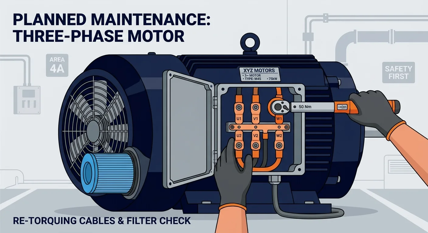
Most three-phase failures announce themselves first. The craft is noticing.
- Terminations: re-torque to the manufacturer's specification during planned shutdowns. Loose joints heat, heat oxidises, oxidation raises resistance, and the joint gets hotter.
- Cooling: clean filters, check fan operation, verify enclosure ventilation. A drive that's overheating in summer was probably marginal in winter.
- Contactors: inspect contacts for pitting and wear. A contactor that's been switching heavily loaded motors for years is a wear item.
- Cables: look for chafing, heat damage and damaged glands, especially where cables enter moving equipment.
- Drive logs: read them. A log full of past overvoltage events tells you about supply quality before it becomes a stoppage.
- Documentation and spares: keep drawings current and hold the right spare contactor coils, fuses and overload relays. The wrong spare fitted under pressure is its own failure mode.
And one more: a "nuisance trip" is information. Something operated for a reason. Defeating the protection, increasing the setting without calculation, or taping down a contact removes the symptom and keeps the fault. The mechanical encyclopedia is useful when the electrical side checks out and you need to understand the driven machine.
A short diagnostic case
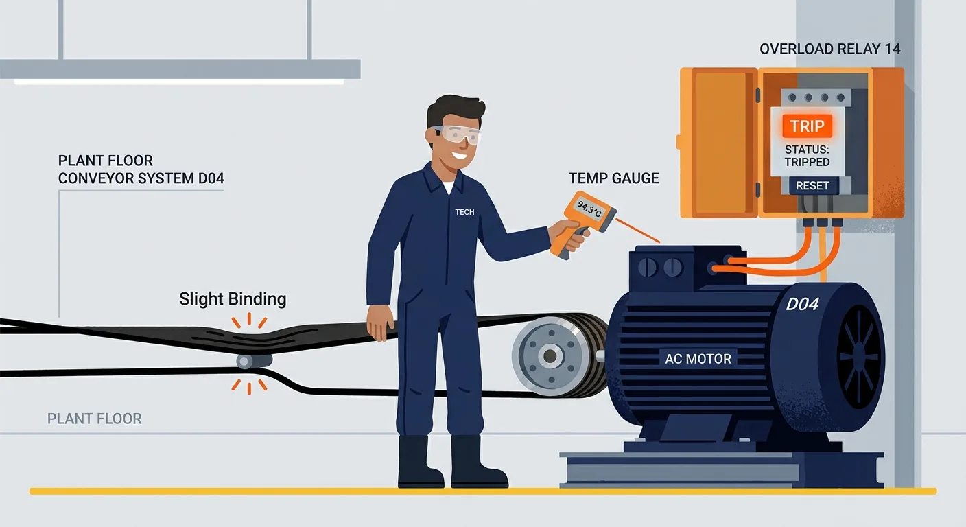
A conveyor motor trips its overload after about ten minutes of running. It starts fine and runs fine until it doesn't. Ten minutes is a thermal timescale, so think heat, not a hard fault.
The hypotheses worth testing:
- Mechanical load. Is the conveyor binding, overfilled or misaligned? A rising load raises current until the overload operates. Compare current with the conveyor empty and loaded.
- Voltage imbalance. Clamp all three lines and compare. An imbalance across the lines produces disproportionate heating in the motor. Check the supply and the terminations.
- Insulation. A winding with degrading insulation can leak enough to heat without failing outright. Insulation resistance testing, done by a qualified person, separates this from the other causes.
- Ventilation. Is the motor's cooling fan intact? Is the motor buried in dust? Is the enclosure clogged?
- Overload setting. Is the relay set to the nameplate full-load current for the actual connection (star or delta)? A relay set for the wrong connection will trip a healthy motor.
The measurements a qualified technician would take: line currents on all three phases, line-to-line voltages, the overload relay setting against the nameplate, and a temperature check on the motor frame and terminations. If you're also tracking supply quality on the low-voltage side of a site vehicle or generator, the charging system check and the battery calculator are handy for the DC side of the same story.
FAQ
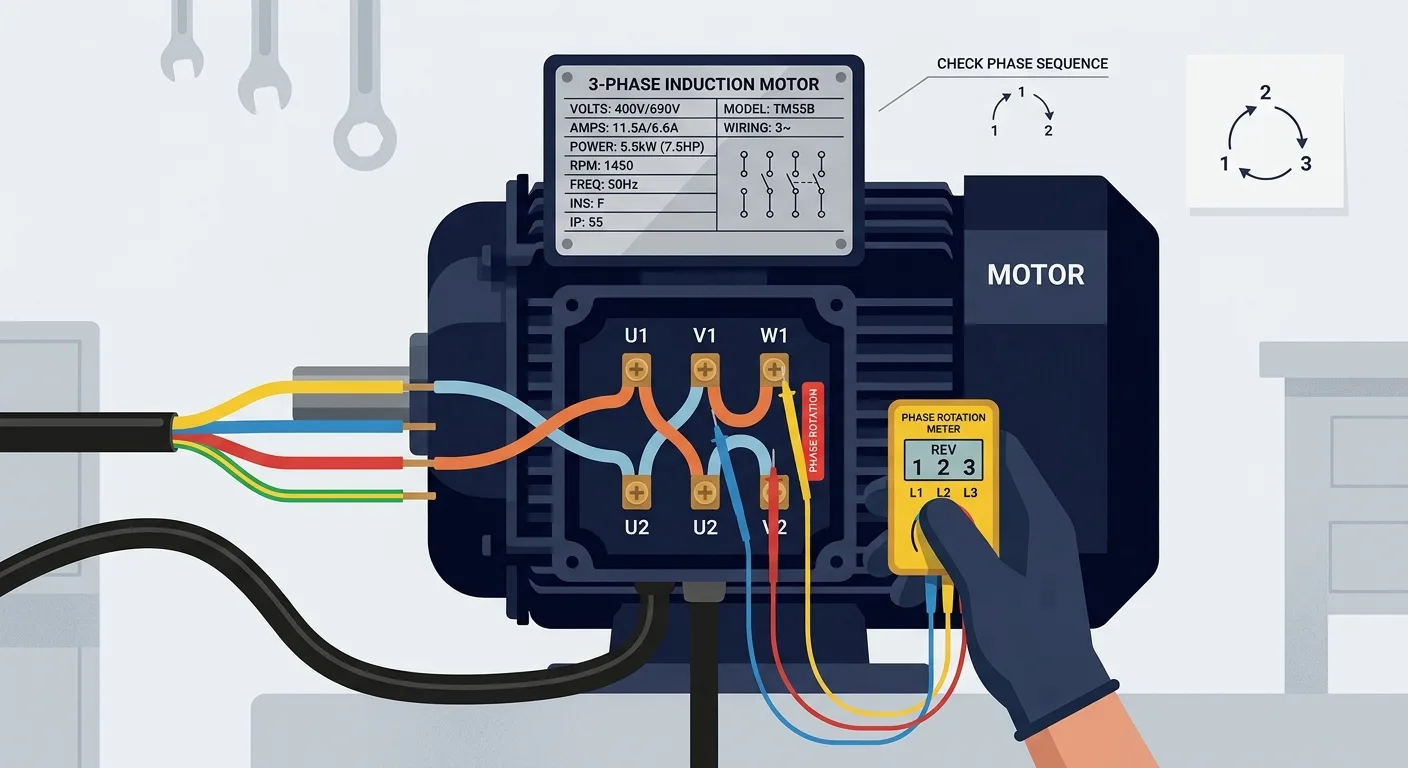
Why does a three-phase motor run backwards? Two of the line conductors are swapped. Reverse any two and the rotating field reverses. Check phase sequence with a meter before first run rather than discovering it on a full conveyor.
Can I use a VFD on any motor? Not automatically. Motor insulation, cooling at low speed, bearing currents and cable length all matter, and the drive and motor manufacturers publish the limits. Check the documentation for both before you fit a drive to an existing motor.
Why does the drive trip on an earth fault? Something is leaking current to earth: motor winding insulation, a damaged cable, moisture in a terminal box, or a wiring error. The drive is telling you a fault current path exists. Find it before you reset.
Why is my neutral current not zero on a "three-phase" circuit? Because the load isn't balanced. Single-phase equipment connected phase-to-neutral, or an unevenly loaded distribution board, will produce neutral current. That's normal up to the design limit and a symptom beyond it.
Do I need to measure all three phases? Yes, if you want to find anything. A single-phase reading tells you almost nothing about a three-phase problem.
The takeaway
Three-phase work rewards a system-level view: know which voltage you're measuring, compare all three lines, understand which device protects what, and treat every trip as a message rather than an inconvenience. Verify every value against the nameplate, the drawings, the manufacturer's documentation and the applicable standard. And leave the live work to the people authorised and equipped to do it.