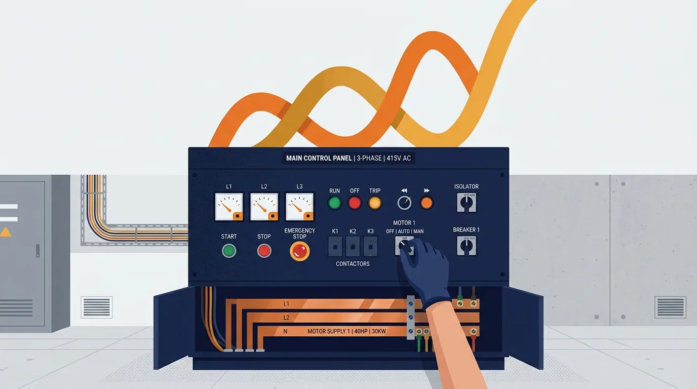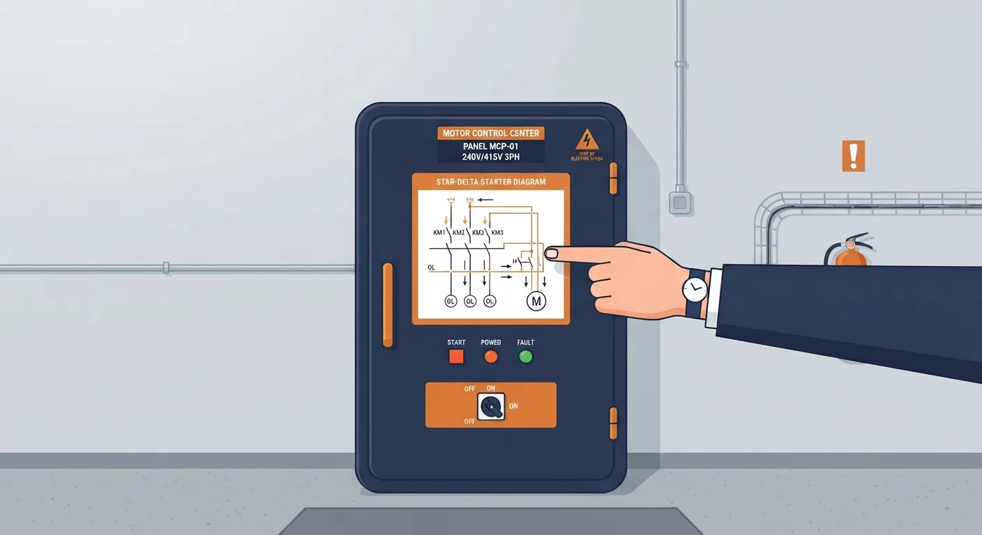
You are standing in front of a motor control panel. The motor runs for ten minutes, the overload trips, and someone says "it's wired wrong, check the star delta connection." Or you are looking at a nameplate that says 400 V delta / 690 V star and wondering which one applies to your supply. This article covers the three-phase side of an industrial installation: the motor, its starter or drive, the protection around it and the panel it lives in. It helps you make one decision or diagnosis: is this connection and its protection set up correctly for the supply and the load, and if not, where do I look first?
Live work and final verification belong to qualified, authorised personnel under the site's safety rules and permit-to-work system. Nothing here replaces that.
Three-phase fundamentals
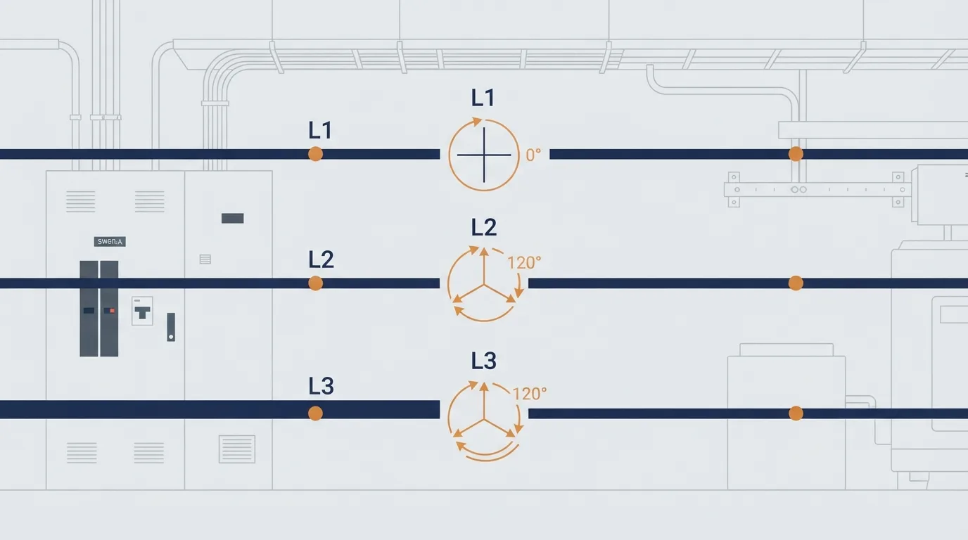
A three-phase supply gives you three line conductors, often called L1, L2 and L3, plus a neutral and a protective earth. The voltages between any two lines are the line voltages, and in a healthy system they are equal in magnitude and separated in phase by 120 degrees. The voltage between any one line and the neutral is the phase voltage.
On a common European distribution, an illustrative relationship is 400 V between lines and 230 V between line and neutral. The ratio is the square root of three: 400 divided by 1.732 gives about 231 V. That example is just that, an example. Verify the actual voltage on site with a proven tester before you assume anything.
When a load draws the same current in all three lines, it is balanced. A three-phase motor is close to balanced when it is healthy, which is why the neutral is usually not needed at the motor. Phase sequence matters too: swap any two lines and the rotating field reverses, so the motor runs backwards. That is the whole explanation for the classic "why is the pump spinning the wrong way" call.
Star and delta in plain terms
Each motor has three windings. In a star (also called wye) connection, one end of each winding is joined at a common point, the star point, and the other ends go to the three lines. In a delta connection, the windings are connected end to end in a triangle, and each line connects to one corner.
Here is the part technicians actually need: the winding sees different voltage and current in each configuration.
| Star | Delta | |
|---|---|---|
| Voltage across each winding | Line voltage divided by √3 | Full line voltage |
| Current in each winding | Same as the line current | Line current divided by √3 |
Work it through with the illustrative 400 V supply. In star, each winding sees 400 / 1.732, about 231 V. In delta, each winding sees the full 400 V. That is why a motor rated 400 V delta / 690 V star is intended to run in delta on a 400 V supply: the winding is designed for 400 V. Connect it in star on that supply and each winding only gets about 231 V, so the motor produces far less torque and will likely stall or draw heavy current under load. The reverse mistake, delta on a supply the winding is not rated for, overheats the winding.
This is the heart of star delta starting: start in star to limit the voltage and current per winding, then switch to delta for full running torque. If you want the formulas laid out properly rather than in a table, the electrical formulas reference is a good place to sit with them.
Motor starters and protection
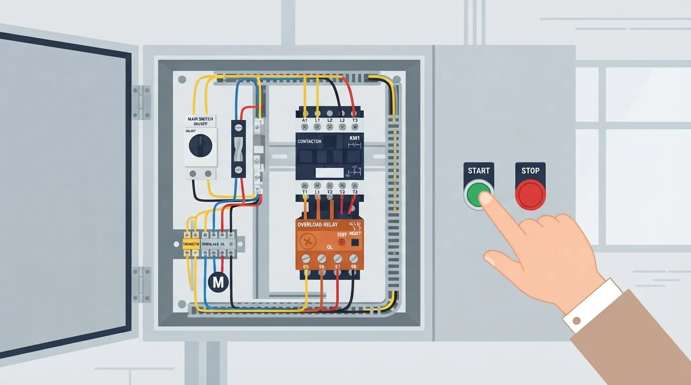
A direct-on-line starter is the simplest arrangement: a contactor closes and puts full line voltage on the motor. It gives full starting torque and a large starting current, which is fine for small motors and hard on the supply for big ones.
Each device in the starter has a job. The contactor is a switching device, not a protector. The overload relay protects the motor from sustained overcurrent by sensing current, usually through thermal or electronic elements. Fuses and circuit breakers protect the cable and the installation from short circuit and earth fault. The person is protected by earthing, bonding and the right protective device disconnecting a fault quickly. Coordination matters because each device must do its job without the other one tripping first in a way that leaves a gap.
When a motor will not start, work through this order: supply present and correct at the isolator, control circuit healthy, emergency stop and interlocks made, contactor coil actually pulling in, overload not tripped, then the motor and the mechanical load. Nine times out of ten the fault is in that list before you get to the motor.
Variable frequency drives
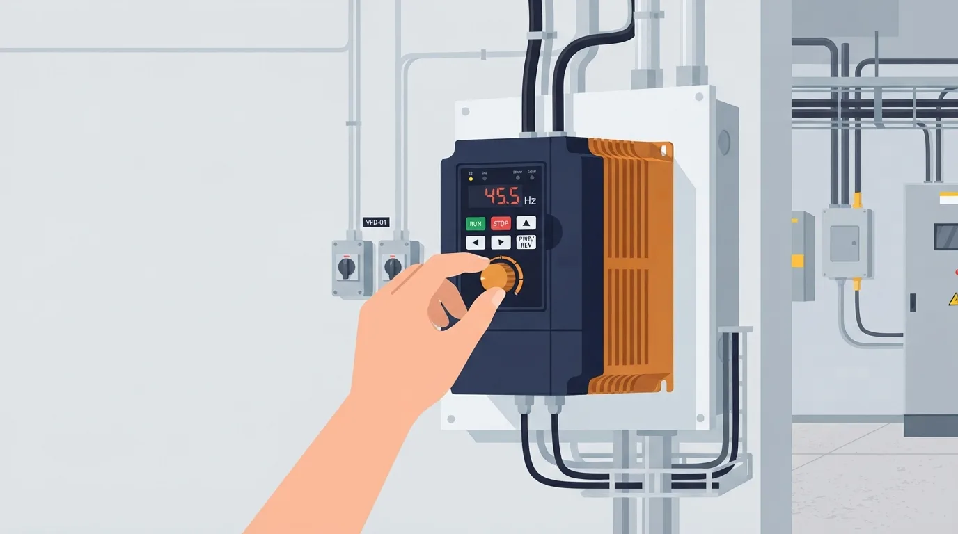
A VFD rectifies the incoming AC to a DC link and then switches it back into a variable-frequency, variable-voltage output. That lets you control motor speed and starting current instead of accepting whatever the supply gives you.
The output is not a clean sine wave. It is a fast-switching waveform, and that is why cable type, cable length and earthing matter. Long motor cables and poor screening raise the risk of earth leakage currents, bearing currents and interference. Follow the drive manufacturer's instructions on cable and earthing, not a generic rule of thumb.
Common drive faults come in recognisable families: overcurrent, overvoltage on the DC link (often during deceleration), undervoltage, overheating, earth fault and communication loss. Each points somewhere different. A drive that trips on overvoltage every time a big load stops is telling you about deceleration settings, not about a faulty drive. Parameter numbers, wiring terminals and reset procedures must come from the manufacturer documentation for that model. Guessing them is how drives get damaged.
Earthing and bonding
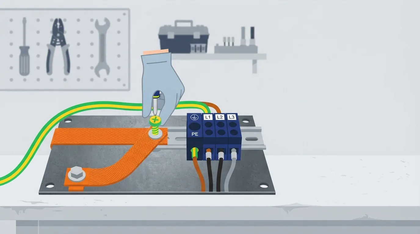
Protective earth gives fault current a low-impedance path back to the source so the protective device operates and disconnects the supply. Equipotential bonding keeps metalwork at the same potential so you do not become part of the circuit. Lose the earth and the protection may never operate, leaving exposed metal live after a fault. That is a safety problem, full stop.
Earth resistance limits are set by the applicable standard and the site procedure. I will not put a number here because the right one depends on your installation and earthing system. Check the standard and your site documentation.
Panel diagnostics
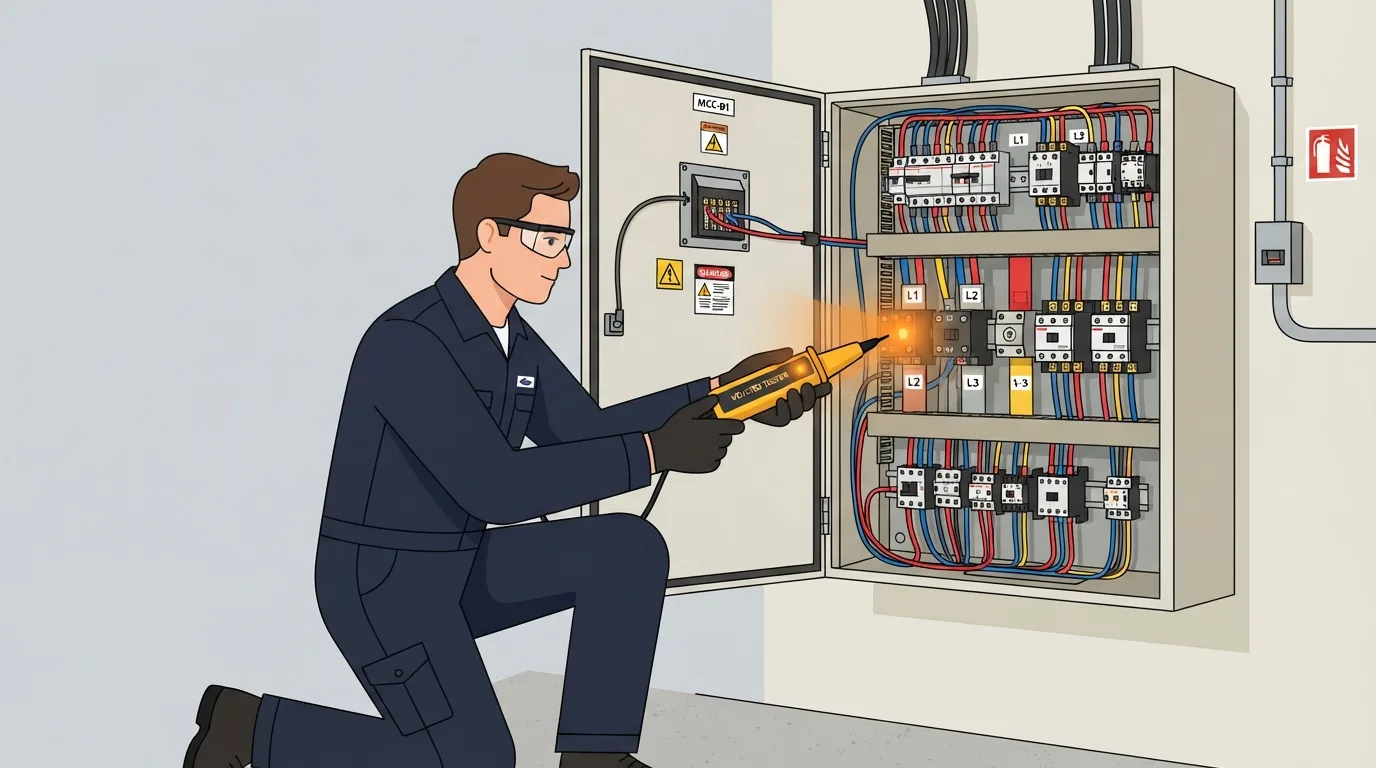
Work in order. Identify the panel and its isolation point from the drawing. Read the labels before touching anything. Confirm absence of voltage with a proven tester, and prove the tester on a known source before and after.
Then inspect. Look for heat discolouration, loose terminations, burnt contacts and signs of arcing. Check the control supply. Check interlocks. Only then test the circuit. Thermal imaging and insulation resistance testing are qualified tasks done with the right instrument and the right procedure; they are not something to improvise on a live panel. The electrical diagnostics guides and electrical measurement guides go deeper on the instrument side.
Safety first: LOTO and arc flash
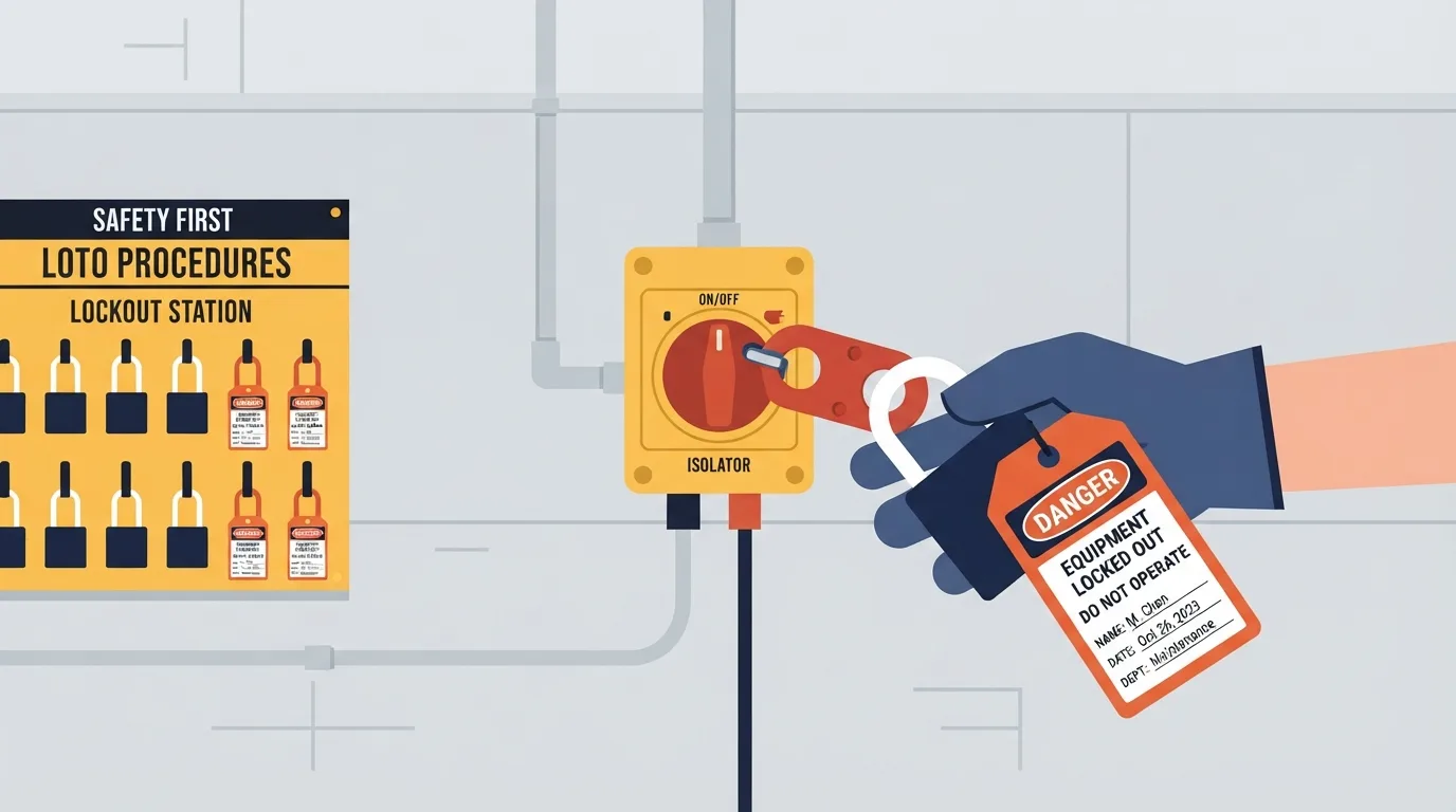
Lockout/tagout means isolate, lock, tag, prove dead, and discharge stored energy such as capacitors in a drive or a battery-backed circuit. Prove dead with a tester you trust, on a source you know works. Wear the PPE your site requires, respect arc-flash boundaries, never work alone on live equipment and never bypass an interlock to "get it running."
This section is not a substitute for your site's permit-to-work and electrical safety programme. It is a reminder of the shape of it.
Preventive maintenance
The unglamorous checks catch most failures: terminations tight and cool, cooling fans and filters clear, contactor contacts not pitted, cable condition sound, drive logs reviewed for creeping trends. Keep documentation current and keep spares for the parts that fail.
One thing worth saying plainly: a "nuisance trip" is information, not an inconvenience to defeat. Someone who disables an overload has removed the one device protecting the motor.
A short diagnostic case
A motor trips its overload after running for ten minutes. That timing is a clue: it is not a dead short, it is something building up.
Hypotheses to work through: mechanical load increasing (a bearing or a blocked impeller), supply voltage imbalance, winding insulation degrading, blocked motor cooling, or an overload set too low for the actual duty. A qualified technician would measure line currents on all three phases under load, check voltage balance, check motor temperature, inspect cooling, and compare the overload setting to the motor nameplate. Each measurement narrows the list. Only then do you touch the setting.
FAQ
Why does a three-phase motor run backwards? Two line conductors are swapped. Reverse any two and the rotating field reverses. Check phase sequence before you reconnect.
Can I use a VFD on any motor? Not always. Inverter-duty motors are built for it. Standard motors may need derating or extra protection, and the manufacturer documentation decides.
Why does the drive trip on an earth fault? Current is reaching earth somewhere it should not: cable damage, moisture, a failing winding or a screening problem. Find the cause, do not just reset it.
Why does a star-connected motor have low torque? Each winding sees line voltage divided by √3, so the available torque drops sharply. That is the point of star for starting, and the reason you switch to delta to run.
For related electrical background, the Electrical Hub and the electrical concepts library are useful starting points. If you want to test yourself on the basics, try the electrical quiz.
Takeaway
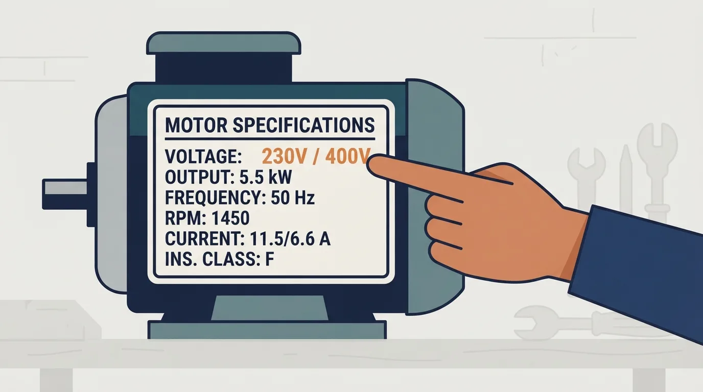
Star and delta change the voltage and current each winding sees, and that single fact explains starting, running and most of the wiring mistakes you will meet. Verify every voltage, setting and limit against the nameplate, the standard and the site documentation, and leave live work to the people authorised and equipped for it.