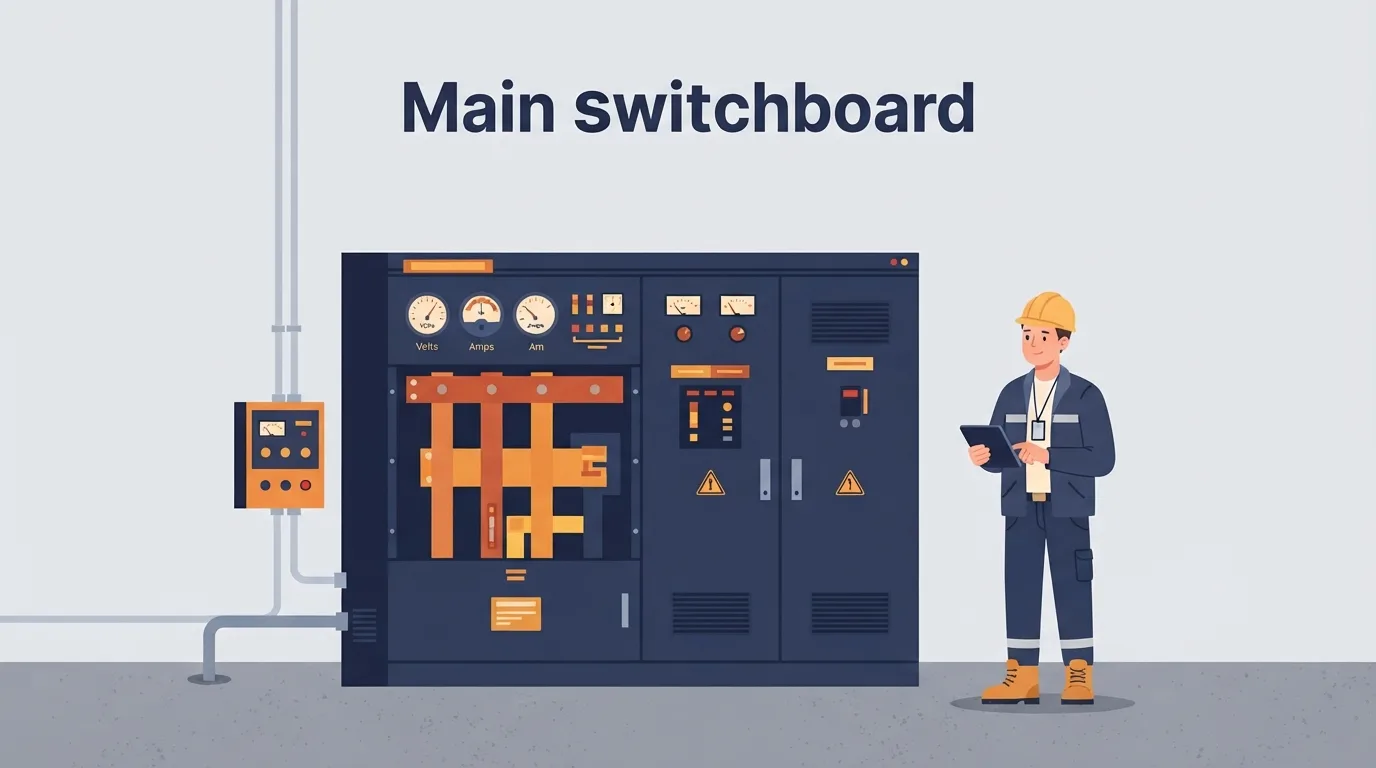
Most electrical arguments in a plant start with someone pointing at a panel and saying "it's three-phase, it should be fine." That sentence hides a lot. This article covers the system-level difference between single-phase and three-phase supply as you will meet it in an industrial installation: the panel, the motor feeder, the starter, the drive, and the protective earth that ties it all together. It is written for maintenance technicians, industrial electricians and engineers who need the picture, not a physics lecture.
By the end you should be able to look at a nameplate or a drawing and answer one practical question: what kind of supply does this load actually need, and what does a trip on it tell me? Everything here is background for diagnosis. Live work, isolation, final verification and any arc-flash decision belong to qualified, authorised personnel working under the site's safety rules, permit-to-work system and electrical safety programme. Nothing in this article is an instruction to work live.
Three-phase fundamentals
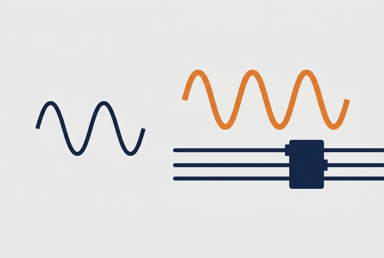
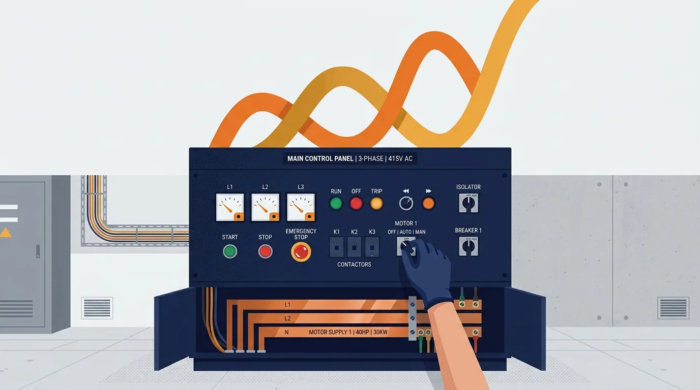
A single-phase circuit gives you one alternating voltage between a line conductor and a neutral (or between two lines, in some arrangements). A three-phase system gives you three line conductors whose voltages are offset in time from each other. That offset is the whole point: the total power delivered stays nearly constant through the cycle, instead of dropping to zero twice per cycle the way single-phase power does.
Take the common European industrial arrangement as an illustration only: a 400 V line-to-line system with 230 V from any line to neutral. The ratio between those two numbers is fixed by geometry, roughly the square root of three. Your site may run something different entirely. Verify the actual values on the nameplate, the panel schedule and the drawings before you assume anything.
Terminology matters here, and people mix it up constantly:
- Phase (line) conductor: one of the three live supply conductors.
- Neutral: the conductor that provides a return path in a star-connected system. It is not the same thing as earth.
- Protective earth (PE): the safety conductor bonded to exposed metalwork. It carries fault current only when something goes wrong.
A balanced load draws roughly equal current on all three lines. Motors are naturally balanced. A panel full of single-phase office loads hanging off one phase is not, and that imbalance shows up as current in the neutral and as voltage differences between phases.
Phase sequence is the order in which the three phases reach their peak. It matters because a three-phase induction motor's direction of rotation is set by that sequence. Swap any two line conductors and the motor runs backwards. That is useful when you need to reverse a pump, and disastrous if you do it by accident on a conveyor.
Star and delta describe how the motor windings are connected. In star, each winding sees the phase-to-neutral voltage; in delta, each winding sees the full line-to-line voltage. That is why a motor may be rated for both, and why the link bars in the terminal box must match the supply. Get it wrong and the motor will either run weak or draw far too much current. The connection diagram on the inside of the terminal box cover is the authority, not memory.
Motor starters and protection
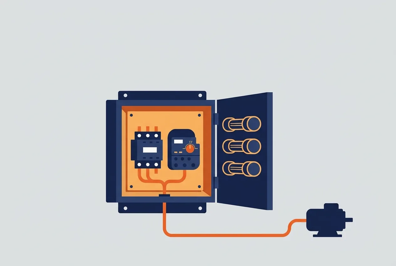
Every protective device in a motor circuit protects something specific. Confusing them is how people end up with a motor that keeps tripping and no idea why.
- Fuses and circuit breakers protect the cable and the installation against short circuit. They are not there to protect the motor winding from overload.
- The contactor is a switching device. It does not protect anything. It just makes and breaks the circuit on command.
- The overload relay protects the motor against sustained overcurrent. It is set to the motor's full-load current from the nameplate, adjusted for the actual installation conditions.
- The protective earth protects people. It gives fault current a low-impedance path back so the protective device operates quickly.
Coordination means these devices are selected so that the one nearest the fault operates first, without nuisance trips upstream and without damage to the contactor. That selection comes from the manufacturer's coordination tables, not from guesswork.
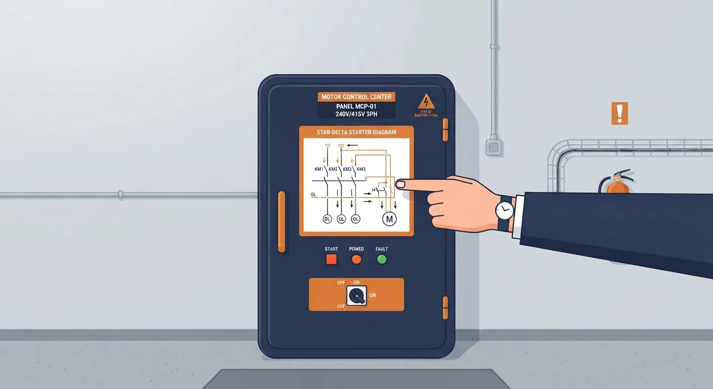
A direct-on-line (DOL) starter is the simplest arrangement: contactor plus overload, full voltage at start. It is fine for small motors and poor for large ones, because starting current is several times running current. Star-delta and soft starters exist to reduce that, and each brings its own checks.
When a motor will not start, work in this order. It saves time and it keeps you out of the panel unnecessarily:
- Supply. Is voltage present at the incoming side, and are all three phases healthy? A lost phase is a classic.
- Control circuit. Is the control supply present, and is the control fuse intact?
- Emergency stop and interlocks. Every interlock in the chain must be made. A guard switch left open looks exactly like a dead motor.
- Contactor coil. Is the coil being commanded, and is it actually pulling in?
- Overload. Has it tripped, and if so, why? Reset it once and watch. Do not reset it repeatedly.
- Motor and load. Is the motor itself faulty, or is the driven equipment seized?
That last step is where a lot of people stop too early. A jammed gearbox and a failed winding both look like "motor won't start" from the front of the panel.
Variable frequency drives
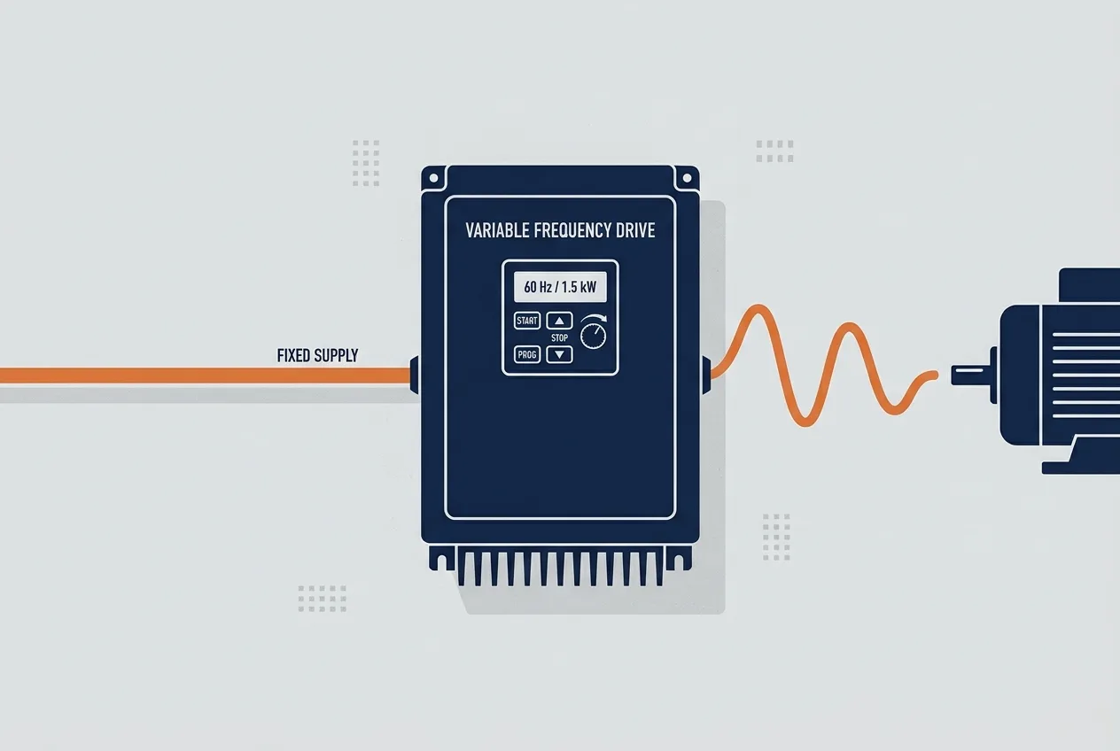
A variable frequency drive (VFD) takes the incoming fixed-frequency supply, rectifies it to a DC link, and then switches it back into a variable-voltage, variable-frequency output. Change the frequency and you change the motor's synchronous speed. That is the entire principle, stated plainly.
What the drive changes is how the motor behaves, and that has consequences for the installation:
- Cable type and length matter. The drive's fast switching produces high-frequency effects on the motor cable. Screened cable, correct earthing at both ends per the manufacturer's instructions, and respect for the stated maximum cable length are not optional refinements. The drive manual will tell you the limits for your frame size.
- Earthing matters more, not less. The drive's earth connection is part of its EMC performance as well as its safety performance.
Common fault categories you will see on a drive display:
- Overcurrent: acceleration too fast, mechanical jam, short circuit, motor fault.
- Overvoltage: deceleration too fast, or the motor being driven by the load (a fan coasting, a conveyor running downhill).
- Undervoltage: supply dip, loose termination, failing contactor.
- Overheating: blocked cooling fan, clogged heatsink, ambient too high, drive overloaded.
- Earth fault: insulation breakdown in the motor or cable, moisture in the terminal box.
- Communication fault: fieldbus cabling, termination, addressing, or a device that dropped off the network.
Every one of those has a parameter or wiring detail behind it, and the answer lives in the manufacturer documentation for your specific drive. Do not apply a parameter from a forum post to a different model. If you are building your understanding of the underlying values, the electrical formulas reference and the free electrical calculators are useful for sanity-checking what the drive is reporting.
Earthing and bonding
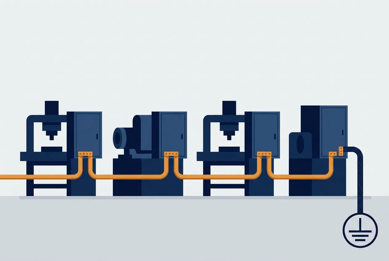
Protective earth and equipotential bonding are the two halves of the same safety idea. Bonding ties all the exposed metalwork together so that no dangerous voltage can exist between two touchable surfaces. The protective earth gives fault current a defined path back to the source so the protective device clears the fault fast.
Lose the earth and nothing appears to change. The plant runs. That is exactly what makes it dangerous: the next insulation fault leaves metalwork live and the protective device never sees enough current to operate.
Earth resistance limits, conductor sizing and testing intervals are defined by the applicable standard and your site's procedure. I am not going to quote a number here, because it depends on your installation type and your jurisdiction, and a wrong number is worse than no number. Check the standard and the site documentation.
Panel diagnostics
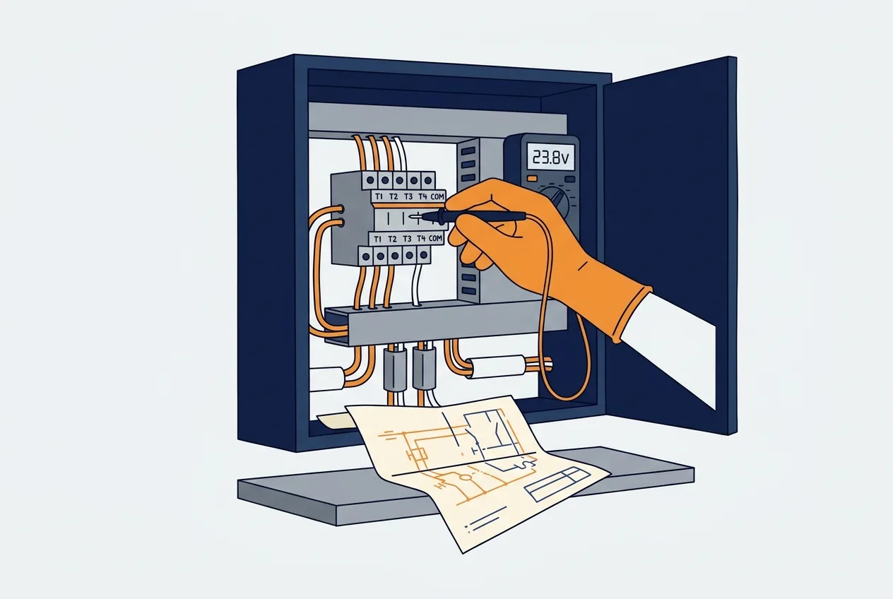
Here is an ordered method that works on almost any industrial panel.
- Identify the panel and the isolation point. Read the label. Confirm which upstream device feeds it.
- Read the drawings and labels. A panel without drawings is a hazard, not a puzzle. If the drawings are missing, that is a finding in itself.
- Confirm absence of voltage with a proven tester. Prove the tester on a known live source before and after. This is the step people skip when they are in a hurry, and it is the step that keeps them alive.
- Inspect before you measure. Look for heat discolouration, loose terminations, burnt contacts, swollen capacitors, insect ingress. Smell the panel. A hot smell tells you where to look.
- Check the control supply. No control voltage, no diagnostics.
- Check interlocks and safety circuits. Confirm each one is made.
- Then test the circuit. With the correct instrument, on the correct range.
Thermal imaging and insulation resistance testing are qualified tasks. They need the right instrument, the right procedure and the right person. The electrical measurement guides cover the instrument side properly, and the electrical diagnostics guides go deeper into fault-finding method.
Safety first: LOTO and arc flash
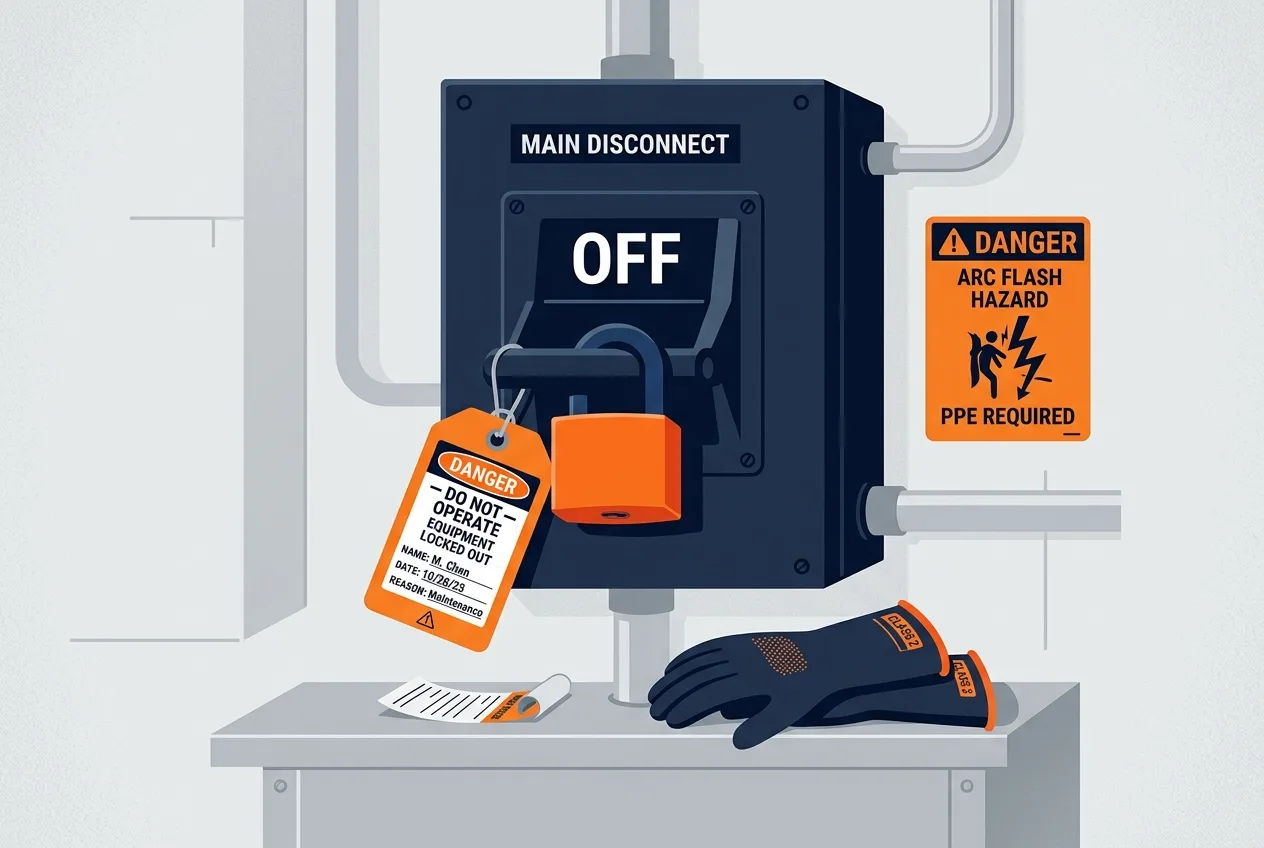
Lockout/tagout (LOTO) is a sequence, not a padlock:
- Identify all energy sources, including stored energy in capacitors, pneumatic and hydraulic accumulators, and suspended loads.
- Isolate.
- Lock and tag with a personal lock.
- Prove dead with a proven tester.
- Discharge stored energy where the equipment requires it, following the manufacturer's procedure.
- Where required by the site's programme, apply an earth.
Wear the PPE your site's risk assessment specifies. Respect arc-flash boundaries, which are calculated for your installation, not copied from a table on the internet. Never work alone on live equipment. Never bypass an interlock to "test it quickly."
This section is not a substitute for your permit-to-work system and your electrical safety programme. It is a reminder of the shape of the thing. If your site has a rule, the rule wins.
Preventive maintenance
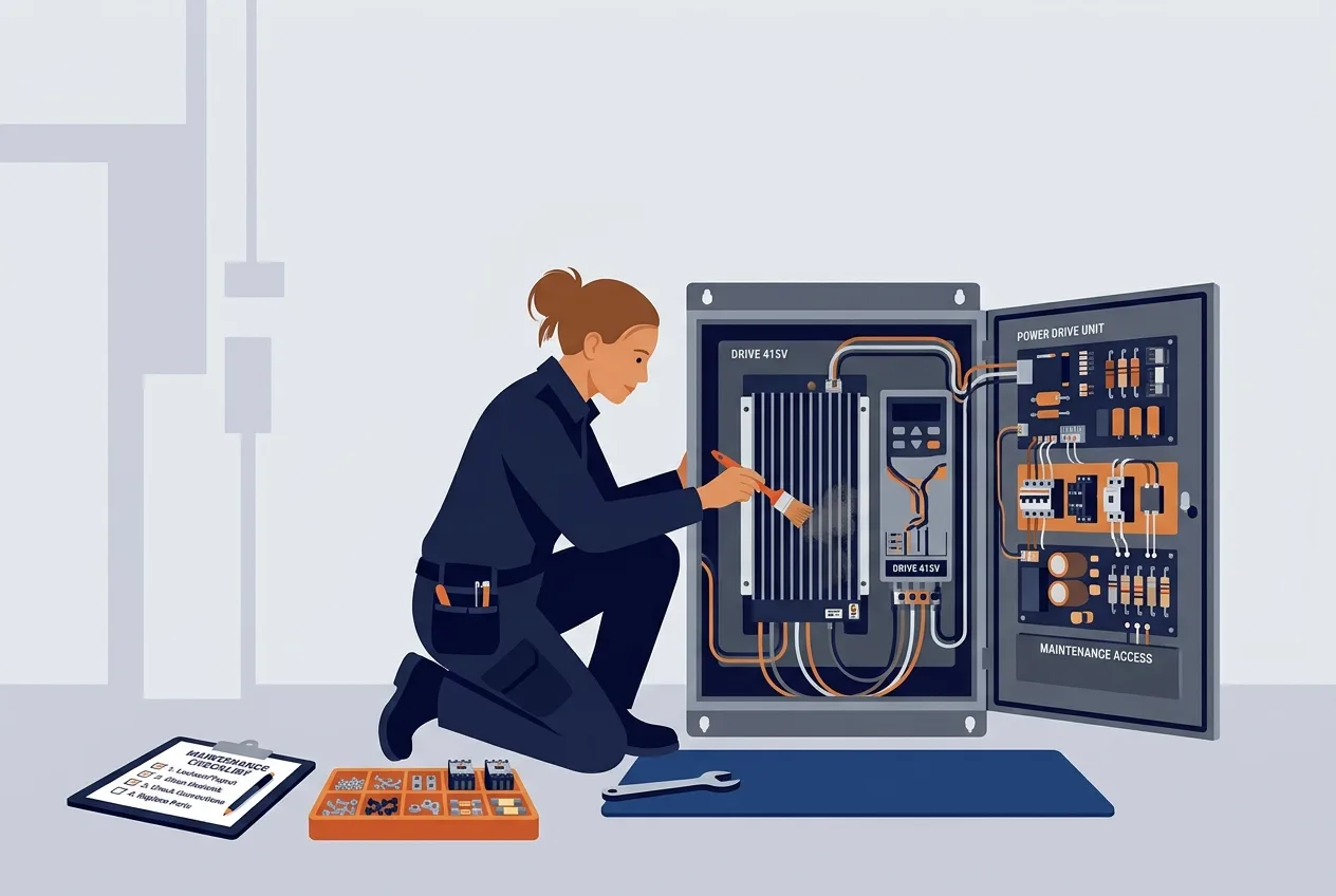
Most panel failures are boring. Loose terminations, blocked filters, worn contactor contacts, cable damage, a drive heatsink full of dust. A periodic check catches them before they become a production stoppage.
Keep documentation current. Keep spare parts matched to the actual installed equipment, not to what the last contractor thought was fitted. If you are working through the fundamentals with a junior technician, the electrical courses and the electrical quiz are a reasonable way to build vocabulary before they touch a panel.
And treat every "nuisance trip" as information. An overload that trips once a month is telling you something is drifting. Defeating it, or winding the setting up, turns a warning into a failure. The setting belongs at the nameplate value, adjusted per the manufacturer's guidance, not at whatever stops the trip.
A short diagnostic case
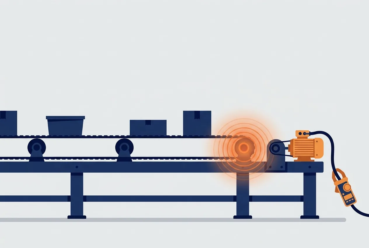
A conveyor motor trips its overload after about ten minutes of running, every time. It restarts fine and runs again. Classic.
The hypotheses, roughly in order of likelihood:
- Mechanical load. Something is binding after the belt warms up and expands, or a bearing is tightening.
- Voltage imbalance. One phase is low, so the motor draws more current on the others.
- Insulation degradation. Leakage current rises as the winding heats.
- Ventilation. Cooling fan damaged, or the motor is buried in product.
- Overload setting. Set too low for the actual duty, or set for the wrong motor.
A qualified technician would measure line current on all three phases under load and compare them, check the supply voltage on all three phases, take a thermal image of the motor and the terminations, and compare the overload setting against the nameplate. If the current is balanced and rising steadily, the mechanical load or the winding is the suspect. If one phase is high, look at the supply and the terminations. Insulation testing follows the site's procedure with the correct instrument.
The point is not to guess the answer. The point is to let the measurements narrow the list before you pull the motor.
FAQ
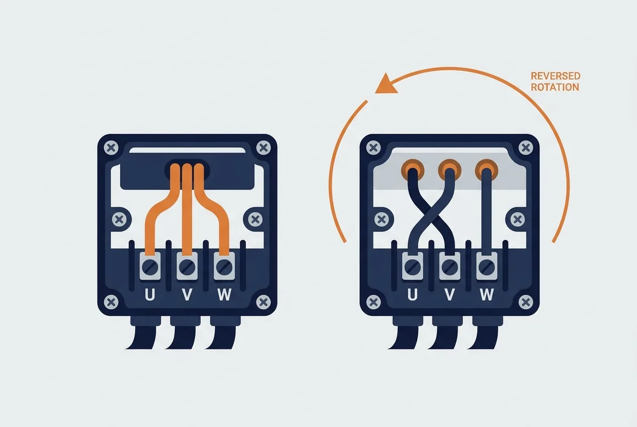
Why does a three-phase motor run backwards? The phase sequence at the motor terminals is reversed. Two line conductors have been swapped somewhere between the supply and the motor. Check at the starter and at the motor terminal box.
Can I use a VFD on any motor? No. Motor insulation, cooling at low speed, bearing currents and cable length all matter. The drive manufacturer and the motor manufacturer both publish limits. Check them for your specific combination.
Why does the drive trip on an earth fault? Something in the motor or the motor cable is leaking current to earth. Moisture in the terminal box, damaged cable, or a failing winding are the usual causes. The drive is doing its job.
Why does the same motor trip in summer but not winter? Ambient temperature affects the overload relay and the motor's own cooling. A setting that was marginal in winter becomes a trip in July.
Is a three-phase supply always cheaper to run? Not automatically. It is more efficient for large motors and it avoids the losses of single-phase conversion, but the actual running cost depends on the load, the tariff and how the equipment is controlled. Compare the real installation, not the label.
One takeaway
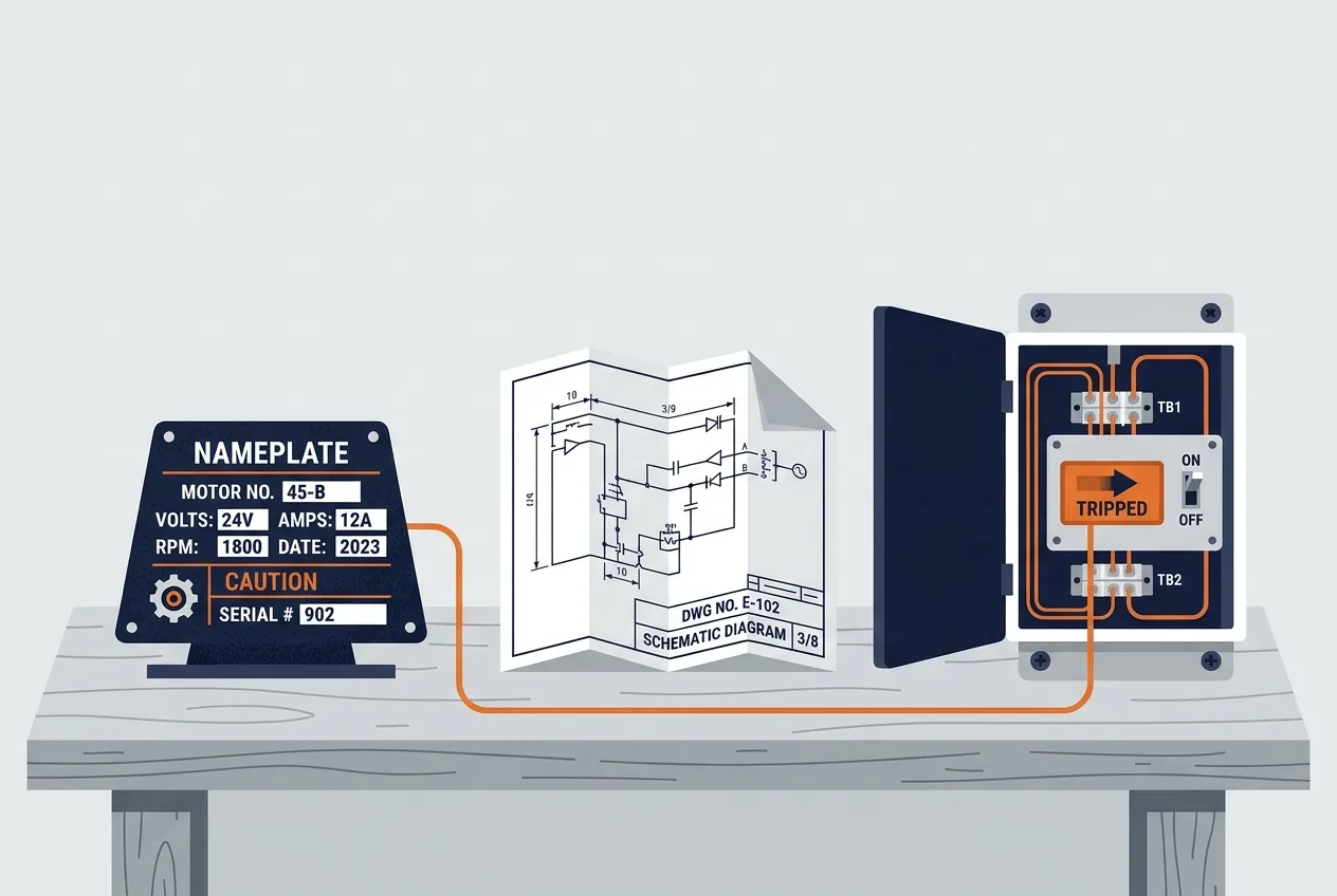
Single-phase and three-phase are not two flavours of the same thing. Three-phase gives you a balanced, rotating supply that suits motors and heavy loads, and it brings its own rules for protection, earthing and phase sequence. Learn to read the nameplate, the drawing and the trip code, and the rest is ordered checking. Everything else, including the final verification, belongs to the qualified person with the permit and the proven tester.
Put this to work on the car: check the numbers with the free battery calculator, follow the step-by-step electrical measurement guides, or start from the Electrical Hub for concepts, formulas and more diagnostics.