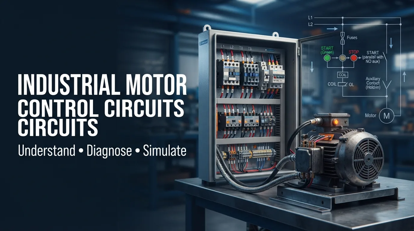
Free Online Motor Control Simulator
Understanding Motor Control Circuits: More Than Just Starting a Motor
Electric motors are everywhere. They power industrial machines, pumps, compressors, conveyor belts, ventilation systems, and countless other applications.
But have you ever wondered what actually happens when someone presses a START button on an industrial control panel?
The motor doesn't simply receive electricity and start rotating. Behind that simple action is an electrical control circuit responsible for managing the starting sequence, stopping operation, and protecting the equipment.
Understanding these circuits is an important skill for electrical technicians, automotive diagnostic specialists, maintenance professionals, and engineering students.
The good news? You don't always need a physical control panel to start learning.
What Is an Industrial Motor Control Circuit?
An industrial motor control circuit is an electrical arrangement designed to control the operation of an electric motor.
It generally involves two complementary sections:
- Power circuit: Supplies electrical energy to the motor.
- Control circuit: Determines when and how the motor operates.
These two sections work together to provide controlled and reliable motor operation.
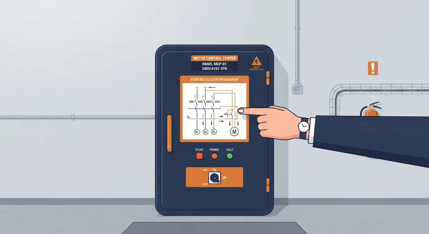
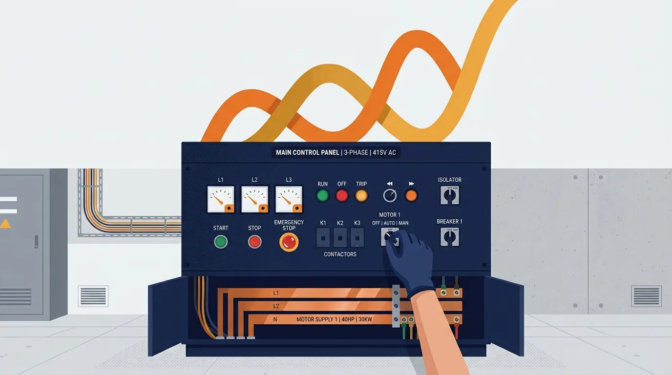
For example, a basic three-phase motor starter may include a circuit breaker, contactor, thermal overload relay, START push button, STOP push button, and an auxiliary contact.
Each component has a specific purpose, and understanding their relationship is essential when troubleshooting electrical systems.
Essential Components of a Motor Control Circuit
Let's look at some of the most important components.
1. Magnetic Contactor
A contactor is an electrically controlled switching device used to connect or disconnect power to a motor.
When its coil receives the appropriate control voltage, the contactor changes state and its main contacts close.
2. Thermal Overload Relay
Motors can draw excessive current under abnormal operating conditions.
An overload relay helps protect the motor by detecting overload conditions and opening the control circuit through its normally closed auxiliary contact.
3. START and STOP Push Buttons
These are the basic commands used by an operator.
- START: Initiates the motor starting sequence.
- STOP: Interrupts the control command and stops the motor.
4. Auxiliary Contacts
Auxiliary contacts are used for control functions such as electrical interlocking and self-holding circuits.
One common application is the contactor holding circuit, which allows a motor to remain running after the operator releases the START button.
Why Should Automotive Technicians Understand Industrial Motor Control?
At first glance, industrial motors and automotive electrical systems may seem like two completely different subjects.
However, they share many fundamental electrical principles.
Both involve:
- Electrical power distribution.
- Switching devices and relays.
- Control signals.
- Protection systems.
- Electrical loads and motors.
- Fault detection and troubleshooting.
For example, understanding how a contactor works can help reinforce your knowledge of automotive relays, while understanding motor protection can improve your approach to diagnosing electrical faults.
The applications are different, but the electrical principles are closely related.
Learn by Doing: Try an Online Motor Control Simulator
Reading electrical diagrams is useful, but observing how a circuit behaves is even more valuable.
This is where simulation becomes particularly interesting.
Control Circuit Studio is a free browser-based electrical control circuit simulator designed to help users explore motor control concepts in a more practical way.
Instead of relying exclusively on theoretical explanations, you can explore electrical control circuits and develop a better understanding of how their components interact.
Whether you're studying electrical engineering, learning industrial maintenance, or improving your electrical troubleshooting knowledge, simulation offers another way to approach complex concepts.
Explore Control Circuit Studio
Ready to explore electrical control circuits?
Visit the simulator:
Open Control Circuit Studio – Free Online Motor Control Simulator
Electrical Knowledge Is Built Through Practice
A technician who understands why a motor starts, stops, or fails to operate has a significant advantage when diagnosing electrical problems.
Start with the fundamentals, learn the function of each component, study electrical diagrams, and use simulation to strengthen your understanding.
The more you understand control circuits, the easier it becomes to approach complex electrical systems with confidence.
Explore more automotive electrical and diagnostic guides on AutoTools.