Understanding Automotive Electrical Systems: ECU, Sensors & Wiring
A complete guide to automotive electrical systems, covering batteries, alternators, starters, ECUs, sensors, actuators, wiring diagrams, diagnostics, safety, and the key differences between gasoline and diesel engine electrical systems.
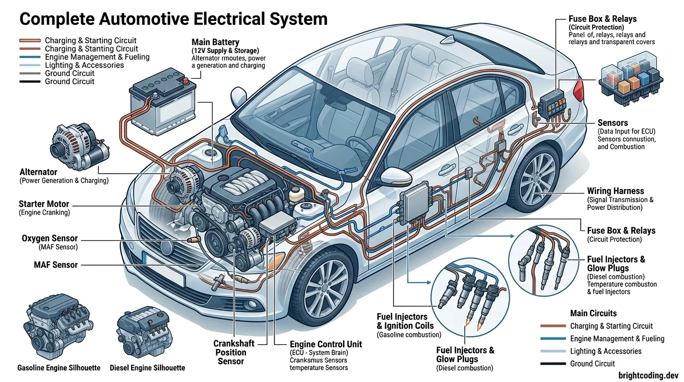
Understanding Automotive Electrical Systems
Electricity is the lifeblood of the modern automobile. While the internal combustion engine still provides the mechanical power that moves most vehicles, it is electricity that makes the engine start, run efficiently, meet emissions standards, and deliver the performance and convenience that drivers expect. Without a reliable electrical system, even the most advanced engine would be nothing more than a complex assembly of metal parts.
This article provides a comprehensive guide to automotive electrical systems, from fundamental principles to advanced diagnostics. Whether you are a student, a technician, or an enthusiast, understanding how electricity powers, controls, and monitors modern vehicles is essential for effective diagnosis and repair.
What Is an Automotive Electrical System?
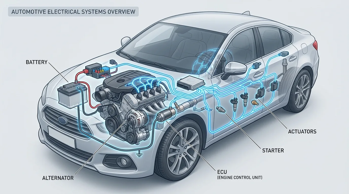
An automotive electrical system is a network of components that generates, stores, distributes, and controls electrical energy throughout a vehicle. It includes the battery, alternator, starter motor, wiring harnesses, fuses, relays, switches, sensors, actuators, and electronic control units (ECUs).
Why Do Gasoline and Diesel Engines Need Electricity?
Both gasoline and diesel engines require electricity for several critical functions:
- Starting: The starter motor uses electrical energy to crank the engine.
- Fuel delivery: Electric fuel pumps and electronically controlled injectors deliver fuel.
- Ignition (gasoline): Spark plugs require high-voltage electricity to ignite the air-fuel mixture.
- Combustion control: ECUs use electrical signals to control injection timing, ignition timing, and other parameters.
- Emissions management: Sensors and actuators work together to reduce harmful exhaust emissions.
The Difference Between Electrical and Electronic Systems
Electrical systems use electricity to perform work, such as turning a motor or lighting a lamp. Electronic systems use electricity to process information and control other systems. Electronic components include microprocessors, sensors, and communication networks.
How Electricity Supports Engine Operation
Electricity supports engine starting, fuel delivery, ignition, combustion control, and emissions management through a complex interaction of components. Sensors monitor engine conditions, the ECU processes this information, and actuators carry out commands to adjust fuel, air, and spark.
The Relationship Between Electrical Components
Components such as sensors, actuators, relays, fuses, and ECUs are interconnected. Fuses protect circuits, relays control high-current loads, sensors provide input, actuators perform actions, and the ECU coordinates everything.
Differences Between Older Mechanical Engines and Modern Electronically Controlled Engines
Older mechanical engines relied on cables, linkages, and mechanical pumps. Modern engines use electronic sensors and actuators controlled by ECUs, allowing precise control of fuel, air, and emissions.
Overview of 12-Volt and 24-Volt Automotive Electrical Systems
Most passenger cars use 12-volt systems, while many commercial vehicles, trucks, and military vehicles use 24-volt systems. Higher voltage allows lower current for the same power, reducing wire size and weight.
Part 1: Fundamentals of Automotive Electricity
1.1 What Is Electricity?
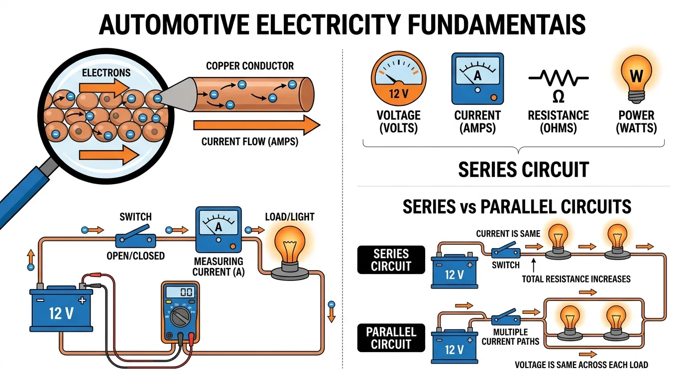
Electricity is the flow of electric charge. In automotive systems, this charge is carried by electrons moving through conductors.
- Electrons and electrical charge: Electrons are negatively charged particles. Their movement creates electrical current.
- Conductors and insulators: Conductors (copper, aluminum) allow current flow. Insulators (rubber, plastic) prevent it.
- Direct current (DC): Automotive systems use DC, where current flows in one direction.
- Alternating current (AC): AC changes direction periodically. It is used inside alternators before rectification.
- Generation, storage, and distribution: The alternator generates electricity, the battery stores it, and wiring distributes it.
1.2 The Four Fundamental Electrical Concepts
A. Voltage (V)
Voltage is electrical potential difference. A typical 12 V vehicle system has a nominal voltage of 12 V, but actual battery voltage may be 12.6 V (engine off) or 13.5–14.5 V (engine running).
B. Current (A)
Current is the flow of electrons. Starter motors require high current (hundreds of amps). Excessive current can damage wires and components.
C. Resistance (Ω)
Resistance opposes current flow. Corrosion increases resistance, reducing performance. Resistance and current are inversely related.
D. Electrical Power (W)
Power is the rate of energy use. P = V × I. A headlight may use 55 W, a starter motor several kilowatts.
1.3 Ohm's Law in Automotive Electricity
Ohm's Law relates voltage, current, and resistance:
- V = I × R
- I = V / R
- R = V / I
- P = V × I
Examples:
- A 6 Ω component at 12 V draws 2 A.
- If voltage is 12 V and current is 3 A, resistance is 4 Ω.
- Voltage drops across connectors indicate resistance.
1.4 Types of Electrical Circuits
- Open circuit: No complete path.
- Closed circuit: Complete path.
- Short to ground: Current bypasses load.
- Short to power: Unwanted power feed.
- Series circuits: One path.
- Parallel circuits: Multiple paths.
- Series-parallel: Combination.
- Ground faults: Unintended ground connection.
- Intermittent faults: Occur under specific conditions.
1.5 Automotive Electrical Symbols
Wiring diagrams use standardized symbols for battery, ground, fuse, relay, switch, resistor, lamp, motor, diode, sensor, injector, ECU, connector, splice, and wire junction. Wire colors, pin numbers, and component codes help identify circuits.
Part 2: The Main Components of an Automotive Electrical System
2.1 The Battery
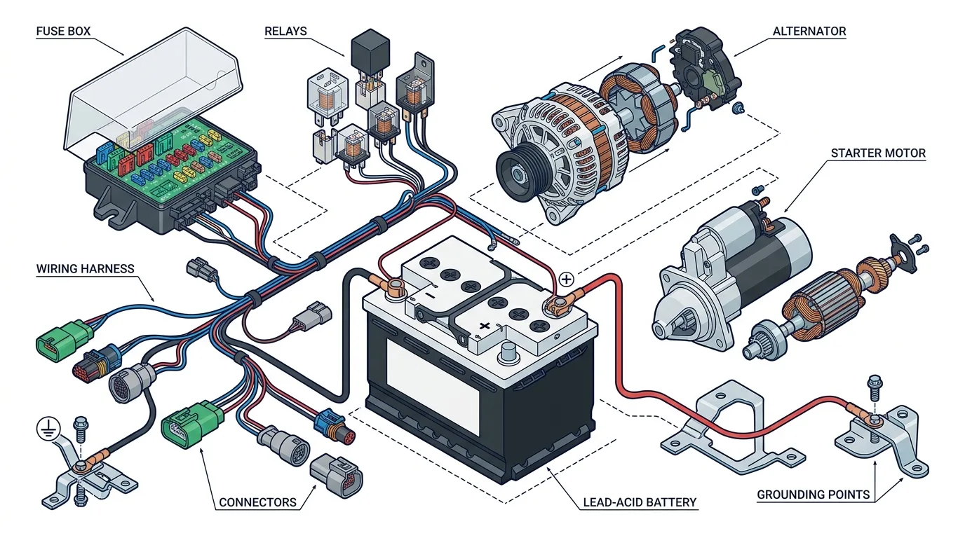
The battery stores electrical energy and provides power for starting and accessories. It has positive and negative terminals, and is rated in cold cranking amps (CCA). Common types include lead-acid, AGM, and EFB. Symptoms of a weak battery include slow cranking and dim lights.
2.2 The Alternator
The alternator converts mechanical energy into electrical energy. It contains a rotor, stator, rectifier bridge, and voltage regulator. It charges the battery and powers electrical loads when the engine runs.
2.3 The Starter Motor
The starter motor cranks the engine. It includes an electric motor, solenoid, pinion gear, and drive mechanism. The starter relay controls the high-current circuit.
2.4 Fuses and Fusible Links
Fuses protect circuits from overcurrent. They come in mini, standard, and cartridge types. Fusible links are special wires that melt under excessive current. Never replace a fuse with a higher-rated one.
2.5 Automotive Relays
Relays use a small current to control a large current. They have a coil and contacts. Terminals 30, 85, 86, and 87 are standard. Relay testing involves checking coil resistance and contact operation.
2.6 Switches, Connectors, and Wiring Harnesses
Switches control circuits. Connectors join wires. Harnesses bundle wires. Wire gauge determines current capacity. Corrosion and loose connections cause faults.
2.7 Automotive Grounding Systems
Ground is the return path for current. Battery negative connects to chassis, engine, and ECU grounds. Poor grounding causes many electrical problems. Voltage-drop testing verifies ground integrity.
Case Study: A corroded engine ground strap caused a no-start condition. Cleaning the connection restored proper operation.
Part 3: Understanding Automotive Wiring Diagrams
3.1 What Is an Automotive Wiring Diagram?
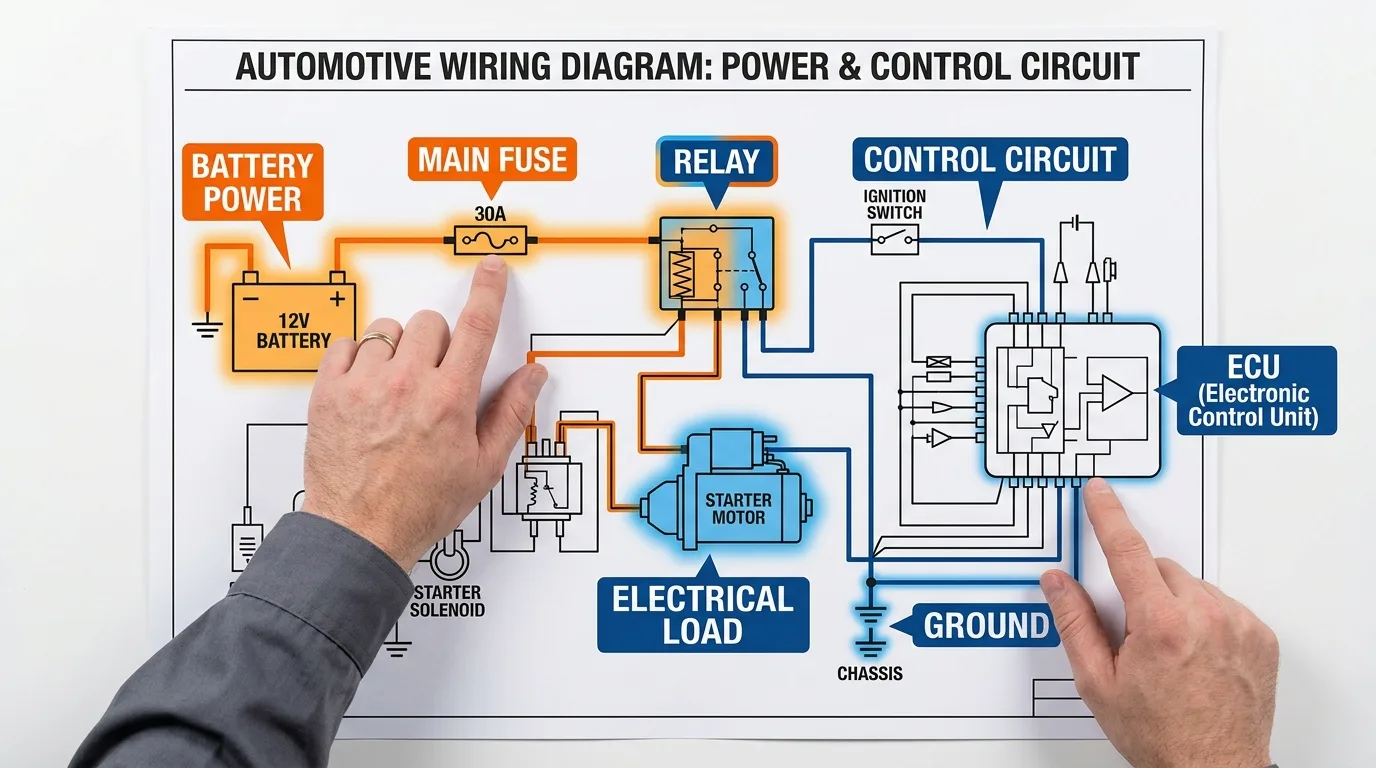
A wiring diagram shows how components are connected. It includes power supplies, grounds, control signals, symbols, and reference numbers.
3.2 How to Read a Wiring Diagram Step by Step
- Identify power source.
- Locate main fuse.
- Identify relay or switch.
- Follow wiring to component.
- Identify control circuit.
- Locate ground.
- Understand operating conditions.
3.3 Power Supply Circuits
- Permanent battery power
- Ignition-switched power
- Accessory power
- ECU power supplies
- Power distribution boxes
3.4 Control Circuits
- Low-current control circuits
- Relay control circuits
- ECU-controlled circuits
- High-side and low-side switching
- Pulse-width modulation (PWM)
- Signal wires vs. power wires
3.5 Common Wiring Diagram Mistakes
- Confusing control and power circuits
- Misidentifying terminals
- Ignoring grounds
- Assuming wire colors are universal
- Replacing components without testing
- Ignoring manufacturer-specific diagrams
Part 4: Engine Control Units (ECUs)
4.1 What Is an ECU?
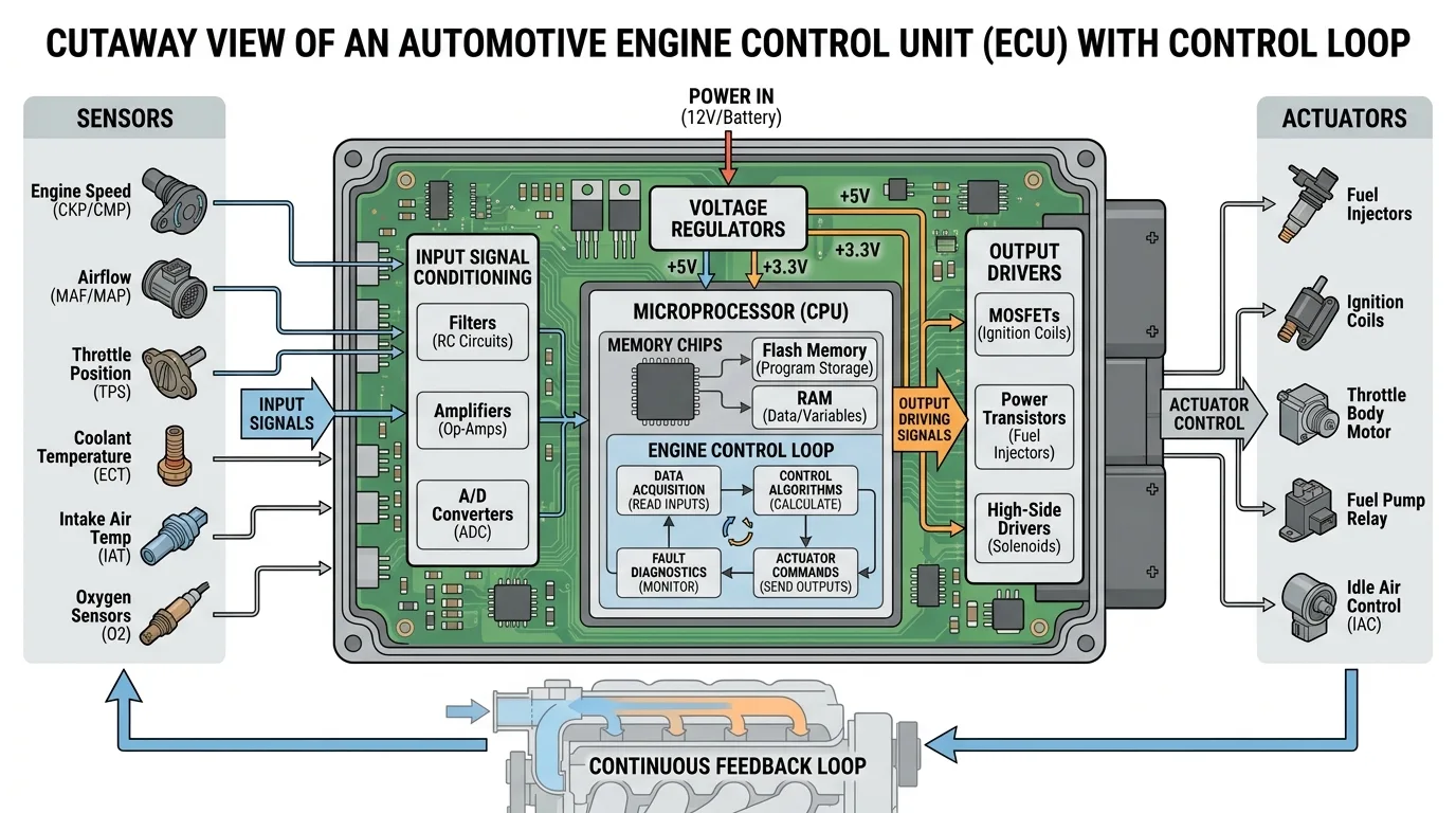
An ECU is an electronic control unit that manages engine operation. It processes sensor inputs and controls actuators.
4.2 Main Components Inside an ECU
- Microprocessor
- Memory
- Voltage regulation circuits
- Input signal conditioning
- Analog-to-digital converters
- Output driver circuits
- Communication interfaces
- Protective circuits
4.3 ECU Inputs and Outputs
Inputs: CKP, CMP, ECT, IAT, MAP, MAF, APP, O2 sensors.
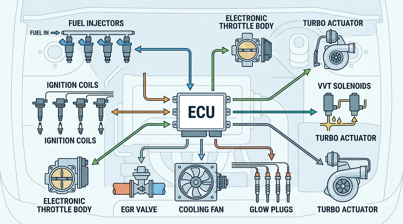
Outputs: Injectors, ignition coils, fuel pump relay, throttle actuator, glow plug module, EGR valve, cooling fan relay, VVT solenoids.
4.4 How an ECU Processes Information
Sensors → ECU Input Circuits → Software Processing → Output Drivers → Actuators → Engine Response. The ECU also monitors feedback and sets diagnostic trouble codes (DTCs).
4.5 ECU Power Supply and Ground Circuits
- Permanent battery supply
- Ignition-switched supply
- ECU main relay
- Power supply fuses
- ECU ground circuits
- Internal voltage regulators
- Consequences of poor power supply
4.6 ECU Communication Networks
- CAN
- LIN
- Diagnostic communication
- Communication between modules
- Symptoms of communication faults
4.7 ECU Failure and Diagnosis
Common causes: water intrusion, voltage spikes, damaged output drivers, corroded connectors, incorrect jump-starting. Distinguish ECU failure from wiring or sensor faults.
Part 5: Sensors in Gasoline and Diesel Engines
5.1 What Is an Automotive Sensor?
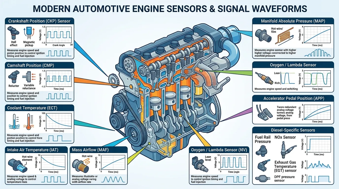
A sensor measures a physical quantity and converts it into an electrical signal. Sensors can be analog or digital, active or passive.
5.2 Crankshaft Position Sensor (CKP)
Measures engine speed and position. Inductive or Hall-effect. Failure causes no-start or misfire.
5.3 Camshaft Position Sensor (CMP)
Detects camshaft position for cylinder identification and VVT.
5.4 Coolant Temperature Sensor (ECT)
Measures coolant temperature. NTC thermistor. Used for cold-start enrichment and fan control.
5.5 Intake Air Temperature Sensor (IAT)
Measures air temperature. Affects air density and fuel calculation.
5.6 Mass Airflow Sensor (MAF)
Measures incoming air mass. Hot-wire or hot-film. Critical for fuel mixture.
5.7 Manifold Absolute Pressure Sensor (MAP)
Measures intake manifold pressure. Used for load calculation, especially in turbocharged engines.
5.8 Oxygen and Lambda Sensors
Measure oxygen content in exhaust. Narrowband or wideband. Used for closed-loop fuel control.
5.9 Accelerator Pedal Position Sensor (APP)
Detects pedal position. Redundant signals for safety. Controls electronic throttle.
5.10 Diesel-Specific Sensors
- Fuel rail pressure sensor
- Boost pressure sensor
- Exhaust gas temperature sensor
- DPF differential pressure sensor
- NOx sensor
- Water-in-fuel sensor
5.11 Sensor Testing and Diagnosis
- Visual inspection
- Check power supply
- Check ground
- Measure signal voltage
- Measure resistance
- Oscilloscope testing
- Scan-tool live data
- Compare with specifications
Part 6: Actuators and Electrical Loads
6.1 What Is an Automotive Actuator?
An actuator converts electrical energy into mechanical action. Examples include solenoids, motors, injectors, and valves.
6.2 Fuel Injectors
Injectors deliver fuel. Solenoid type. ECU controls them. Electrical faults cause misfires.
6.3 Ignition Coils
Produce high voltage for spark. Primary and secondary windings. Coil-on-plug systems. ECU triggers coils.
6.4 Electronic Throttle Body
Motor-driven throttle. Position sensors provide feedback. ECU controls opening.
6.5 EGR Valve
Recirculates exhaust gas. Electronically controlled. Position feedback.
6.6 Cooling Fan Motors
Electric fans cool radiator. Controlled by relays or modules. PWM control possible.
6.7 Glow Plugs and Glow Plug Control Modules
Glow plugs heat combustion chambers in diesel engines. Control module regulates preheating and post-heating.
6.8 Other Electrical Actuators
- Fuel pump
- Idle air control valve
- VVT solenoids
- Turbo actuators
- Swirl flap actuators
- Dosing injectors
- EVAP valves
Part 7: Gasoline Engine Electrical Systems
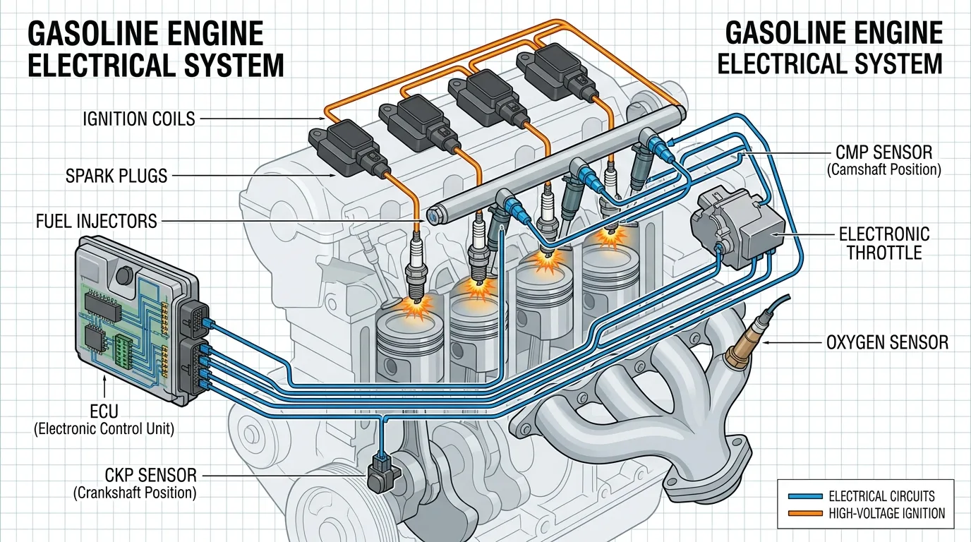
7.1 Overview of a Gasoline Engine
Spark-ignition engine. Four-stroke cycle. Air-fuel mixture. Electrical control essential.
7.2 The Gasoline Engine Ignition System
Battery → ignition switch → ECU → ignition coils → spark plugs. CKP and CMP provide timing.
7.3 Gasoline Fuel Injection Systems
Single-point, multi-point, sequential, direct injection. Fuel pump circuit. Injector control.
7.4 Starting a Gasoline Engine
- Driver turns key or presses start.
- Vehicle authorizes start.
- Starter control circuit activated.
- Starter motor cranks engine.
- CKP and CMP provide position.
- ECU determines injection and ignition.
- Injectors deliver fuel.
- Ignition coils produce sparks.
- Combustion begins.
7.5 Gasoline Engine Management
Air measurement, injection duration, ignition timing, idle speed, closed-loop mixture, knock detection, emissions control, electronic throttle.
7.6 Common Gasoline Engine Electrical Problems
- Cranks but does not start
- No spark
- No injector pulse
- Fuel pump inoperative
- Intermittent stalling
- Misfires
- Difficult cold starting
- Sensor fault codes
Part 8: Diesel Engine Electrical Systems
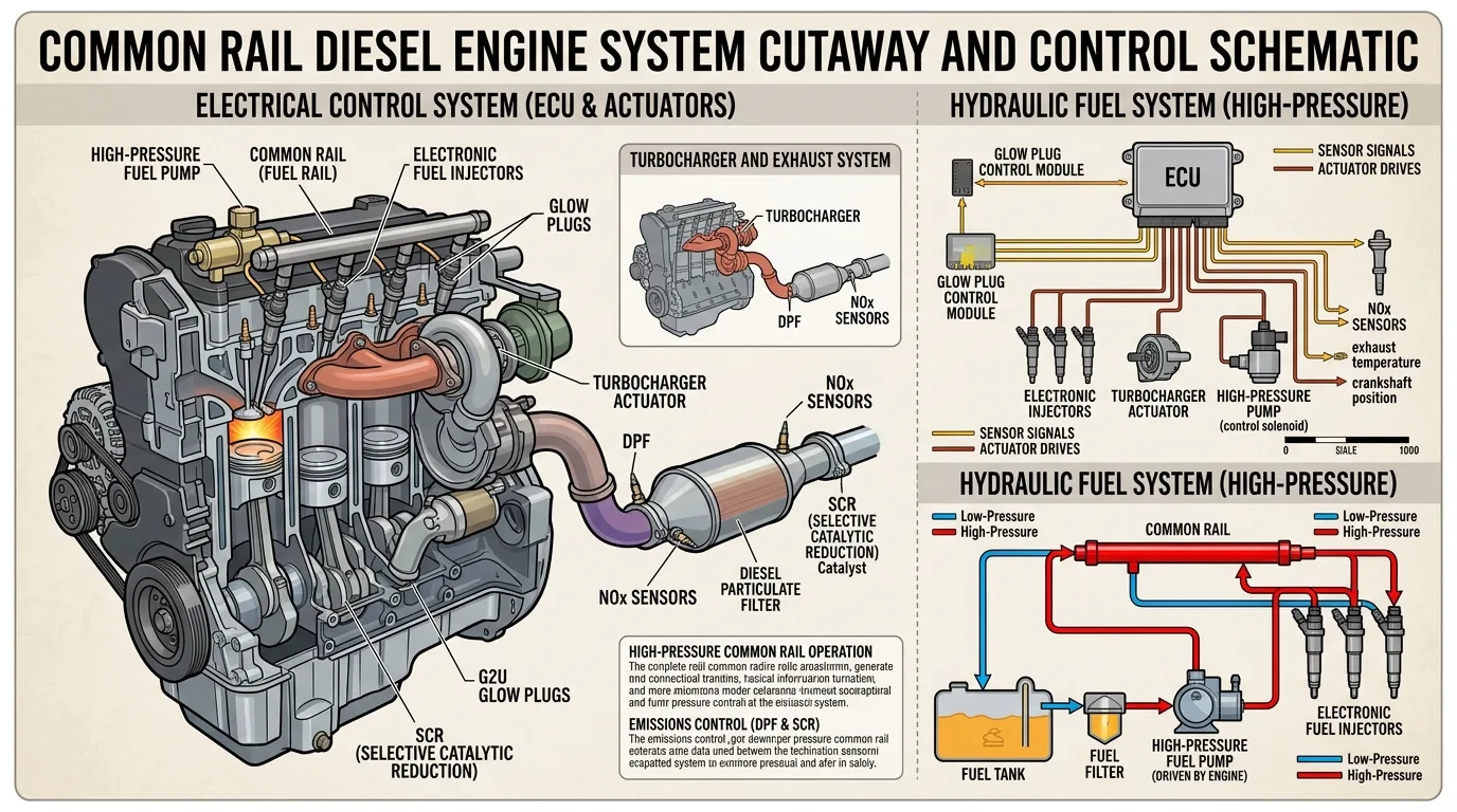
8.1 Overview of a Diesel Engine
Compression ignition. Four-stroke cycle. No spark plugs. Electrical assistance for cold start.
8.2 The Diesel Preheating System
Glow plugs, relay or control module, coolant temperature input, preheating, starting assistance, post-heating.
8.3 Diesel Fuel Injection Systems
Mechanical, distributor pump, unit injector, pump-nozzle, common rail. Low-pressure supply, high-pressure pump, rail, electronic injectors.
8.4 The Diesel ECU and Injection Control
Engine speed and position, rail pressure, injection timing, duration, pilot/main/post injection, multiple events.
8.5 Diesel Common Rail Electrical Circuit
- Battery and power distribution
- Main engine management relay
- ECU power and grounds
- CKP and CMP
- Rail pressure sensor
- Fuel metering valve
- High-pressure pump
- Common rail
- Injectors
- Diagnostic system
8.6 Turbocharger and Diesel Air Management
Boost pressure sensor, MAF, turbo control solenoid, electronic actuator, VGT, intercooler, EGR.
8.7 Diesel Exhaust Aftertreatment Systems
DOC, DPF, differential pressure sensor, EGT sensors, SCR, NOx sensors, DEF dosing, regeneration.
8.8 Common Diesel Engine Electrical Problems
- No crank
- Cranks but no start
- Glow plug failure
- Low rail pressure
- Injector faults
- CKP failure
- Fuel metering valve faults
- Turbo actuator faults
- DPF sensor problems
- ECU communication errors
Part 9: Gasoline vs. Diesel Electrical Systems
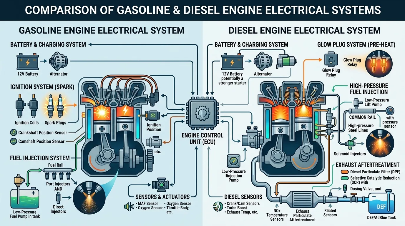
9.1 Main Differences
| Feature | Gasoline Engine | Diesel Engine |
|---|---|---|
| Combustion | Spark ignition | Compression ignition |
| Spark plugs | Used | Generally not used |
| Glow plugs | Not required | Commonly used |
| Fuel injection | Port or direct | Mechanical or electronic |
| Ignition timing | Spark timing | Injection timing |
| Fuel system | Low pressure, high pressure in DI | Low pressure, very high pressure |
| Engine control | Air, fuel, spark, emissions | Air, fuel, injection, emissions |
| Typical sensors | CKP, CMP, MAP/MAF, ECT, O2 | CKP, CMP, MAP/MAF, ECT, rail pressure, NOx |
| Common actuators | Injectors, coils, throttle | Injectors, metering valves, glow plugs, turbo |
| Exhaust treatment | Catalytic converter | DOC, DPF, SCR |
9.3 Components Shared by Both Engine Types
Battery, alternator, starter, fuses, relays, ECU, CKP, CMP, ECT, fuel pump, harnesses, diagnostic connector.
9.4 Components Unique to Particular Engine Designs
Ignition coils and spark plugs (gasoline), glow plugs (diesel), common rail pressure sensors (diesel), high-pressure gasoline injection components (GDI), DPF and SCR components.
Part 10: Automotive Electrical Testing Equipment
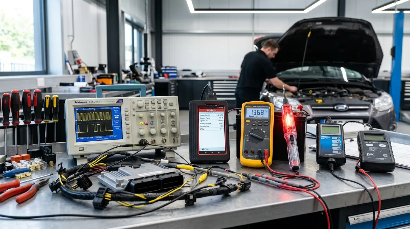
10.1 The Digital Multimeter
Voltage, resistance, continuity, current measurement. Safe use. Correct settings.
10.2 The Automotive Test Light
Conventional and low-current electronic test lights. Avoid damaging sensitive circuits.
10.3 The Automotive Oscilloscope
Voltage waveforms. CKP, CMP, injector, ignition, CAN signals.
10.4 The OBD-II Diagnostic Scanner
Diagnostic connector, fault codes, live data, freeze-frame, readiness monitors.
10.5 Battery and Charging System Testers
State of charge, battery health, cranking performance, charging system tests, voltage drop.
Part 11: Step-by-Step Automotive Electrical Diagnosis
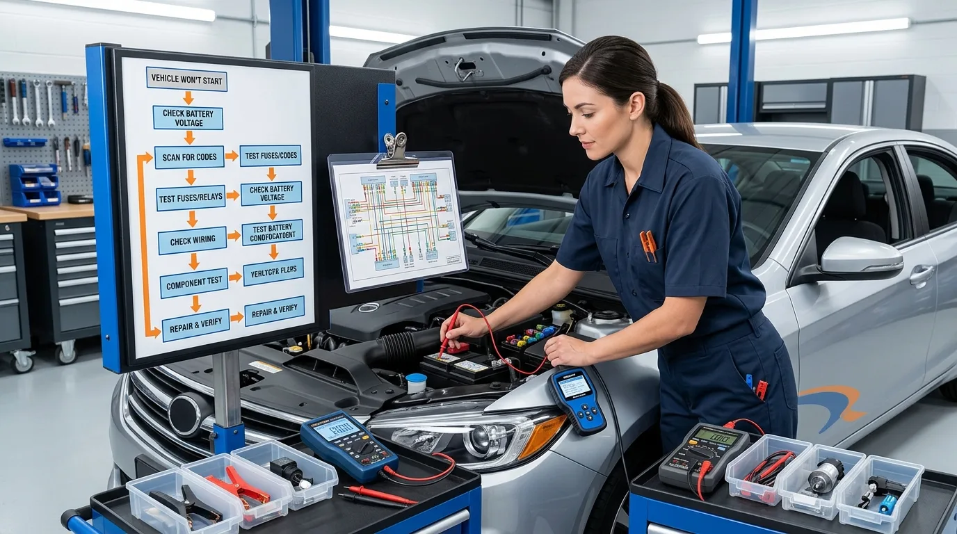
11.1 The Basic Diagnostic Method
- Confirm complaint.
- Identify system.
- Inspect battery and connections.
- Check fuses.
- Read DTCs.
- Consult wiring diagram.
- Verify power and ground.
- Test control circuit.
- Test component.
- Repair fault.
- Clear codes.
- Retest.
11.2 Diagnosing a No-Crank Condition
Battery, terminals, starter power, engine ground, starter relay, ignition switch, interlock, immobilizer, solenoid, starter motor.
11.3 Diagnosing a Crank-No-Start Condition
Gasoline: CKP/CMP signals, spark, injector command, fuel pressure, ECU power/ground, immobilizer.
Diesel: CKP/CMP signals, rail pressure, injector control, low-pressure fuel, glow plugs, ECU power/ground.
11.4 Diagnosing a Blown Fuse
Identify fuse, check diagram, determine failure conditions, inspect wiring, isolate loads, find short, repair cause.
11.5 Diagnosing a Relay-Controlled Component
Identify terminals, verify coil supply and control, check switching, verify contact output, check load and ground.
11.6 Understanding Diagnostic Trouble Codes
DTCs indicate circuit or performance faults. Not always the named component.
11.7 Practical Case Studies
- Gasoline engine cranks but no start.
- Diesel engine fails to start in cold weather.
- Battery discharges overnight.
- Cooling fan does not operate.
- Fuel pump does not receive power.
- ECU does not communicate.
- Fuse blows repeatedly.
- Intermittent CKP fault.
Part 12: Practical Wiring Diagrams and Electrical Circuit Lessons
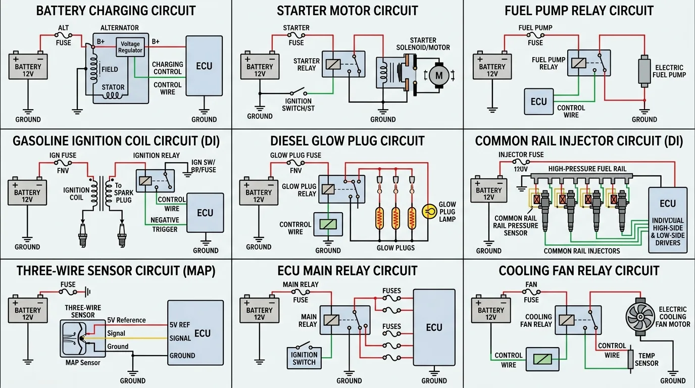
12.1 Battery Charging Circuit
Battery, alternator, voltage regulator, warning indicator, engine ground, battery ground.
12.2 Starter Motor Circuit
Battery positive, main fuse, ignition switch, starter relay, solenoid, starter motor, engine ground.
12.3 Fuel Pump Relay Circuit
Battery, fuse, relay contacts, fuel pump, ground, relay coil, ECU control.
12.4 Gasoline Ignition Coil Circuit
Power supply, ignition coil, ECU trigger, spark plug, ground, engine position signals.
12.5 Diesel Glow Plug Circuit
Battery, high-current fuse, glow plug control module, glow plugs, ECU temperature inputs.
12.6 Common Rail Injector Circuit
ECU power and ground, injector drivers, connectors, CKP/CMP synchronization, rail pressure input, injection authorization.
12.7 Three-Wire Sensor Circuit
5 V reference, sensor ground, signal wire, ECU input.
12.8 ECU Main Relay Circuit
Battery supply, fuse, relay coil, ignition request, ECU power output, ECU grounds.
12.9 Cooling Fan Relay Circuit
Battery power, fuse, relay contacts, fan motor, ECU temperature input, fan control relay, ground.
Part 13: Automotive Electrical Safety
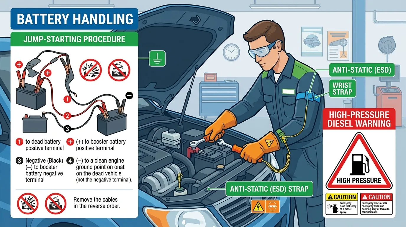
13.1 General Electrical Safety
Switch off ignition, follow battery disconnection procedures, avoid shorting terminals, use insulated tools, protect wiring, never bypass fuses.
13.2 Battery Safety
Lead-acid hazards, hydrogen gas, acid exposure, correct jump-starting, battery replacement, registration.
13.3 ECU and Electronic Component Protection
ESD precautions, correct polarity, avoid voltage spikes, safe test lights, correct probing, programming precautions.
13.4 High-Pressure Diesel Fuel Safety
Common rail pressure danger, never loosen high-pressure lines while running, follow pressure-release procedures, never search for leaks with bare hands.
13.5 When to Disconnect the Battery
Isolation for work, manufacturer shutdown procedures, memory considerations, waiting periods, exceptions for powered tests.
Part 14: Advanced Automotive Electronics
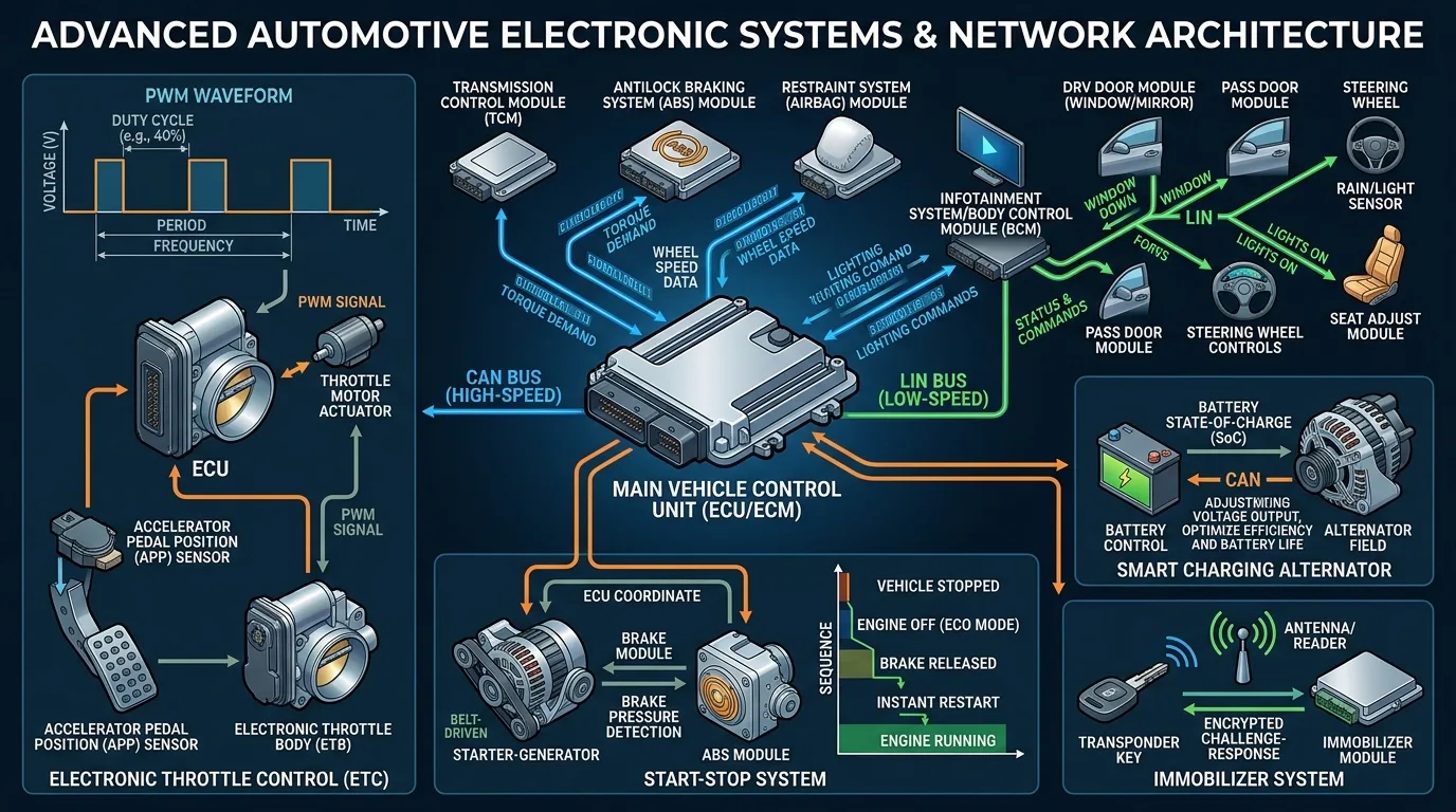
14.1 Pulse-Width Modulation (PWM)
Duty cycle, frequency, ECU control of motors and solenoids.
14.2 CAN Bus Communication
CAN High/Low, topology, termination resistors, faults, diagnostics.
14.3 LIN Bus Communication
Single-wire, typical applications, differences from CAN.
14.4 Electronic Throttle Control
APP sensors, ECU processing, throttle motor, redundant sensors, fail-safe.
14.5 Start-Stop Systems
Battery monitoring, starter control, alternator management, restart conditions.
14.6 Smart Charging Systems
Battery management, intelligent alternator control, current sensors, variable charging voltage.
14.7 Immobilizers and Engine Starting Authorization
Key recognition, immobilizer module, ECU authorization, starter inhibition, fuel/ignition authorization.
Part 15: Practical Exercises and Knowledge Assessment
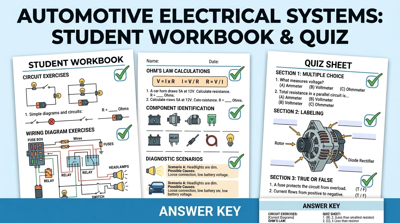
15.1 Basic Electrical Exercises
Calculate current, power, identify circuit types, interpret symbols, calculate voltage drop.
15.2 Wiring Diagram Exercises
Identify fuse, relay, ECU signal wire, ground, current path.
15.3 Component Identification Exercises
Identify battery, alternator, starter, relay, fuse, ECU, CKP, injector, ignition coil, glow plug module.
15.4 Diagnostic Exercises
Present symptoms, ask for next test. Example: gasoline engine cranks but no start. Possible causes: no CKP signal, no injector command, no spark, low fuel pressure, ECU power fault, immobilizer issue.
15.5 Final Quiz
20–30 questions covering fundamentals, batteries, starter circuits, relays, fuses, wiring diagrams, ECU, sensors, actuators, gasoline and diesel systems, diagnostics, and safety. Provide answer key with explanations.
Conclusion: Mastering Automotive Electrical Systems
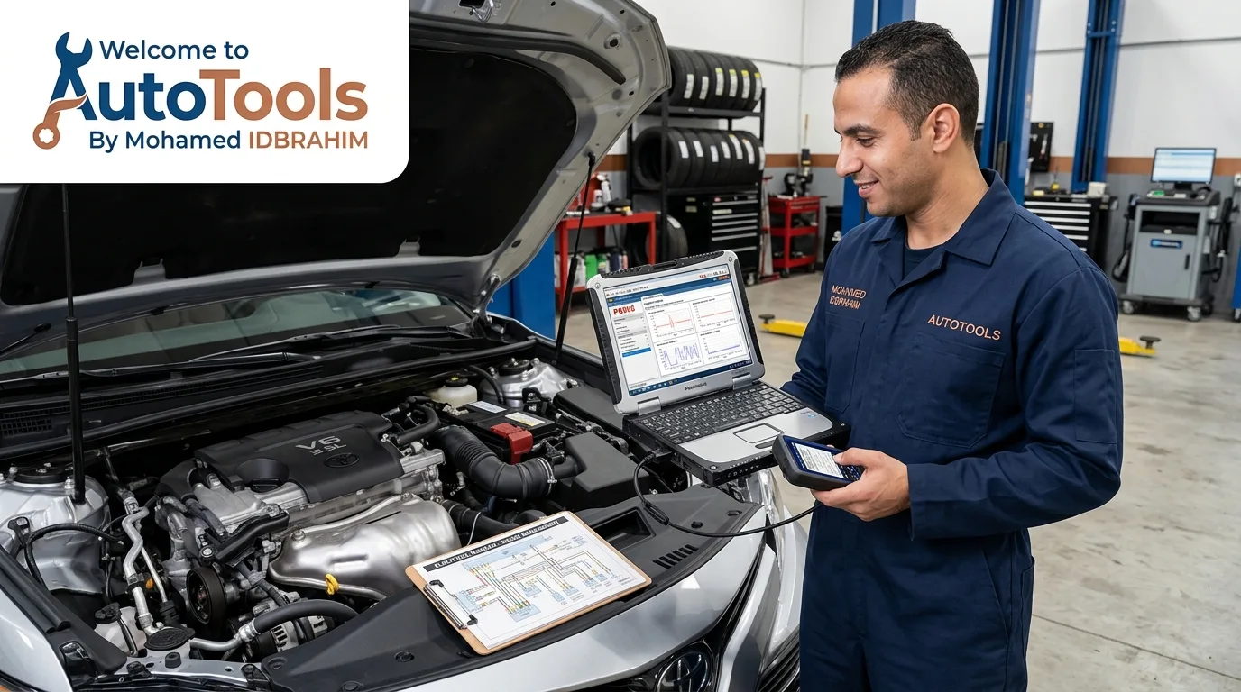
Electrical principles form the foundation of automotive diagnostics. Batteries, alternators, and starter motors provide essential electrical functions. Fuses and relays distribute and protect power. ECUs process sensor information and control actuators. Gasoline and diesel engines share many electrical components but differ in combustion and engine management. Wiring diagrams and systematic testing are essential for accurate diagnosis. Correct diagnostic procedures are more reliable than replacing parts based on symptoms alone.
Learners should progress from basic circuits to complete engine management systems, practicing with wiring diagrams and appropriate diagnostic equipment.
Related articles
10 Diesel Engine Maintenance Tips Every Owner Should Know
Diesel engines reward owners who pay attention. Treat yours well and it can run for hundreds of thousands of miles; neglect a few basics and you will be funding a very expensive repair.
Read the article →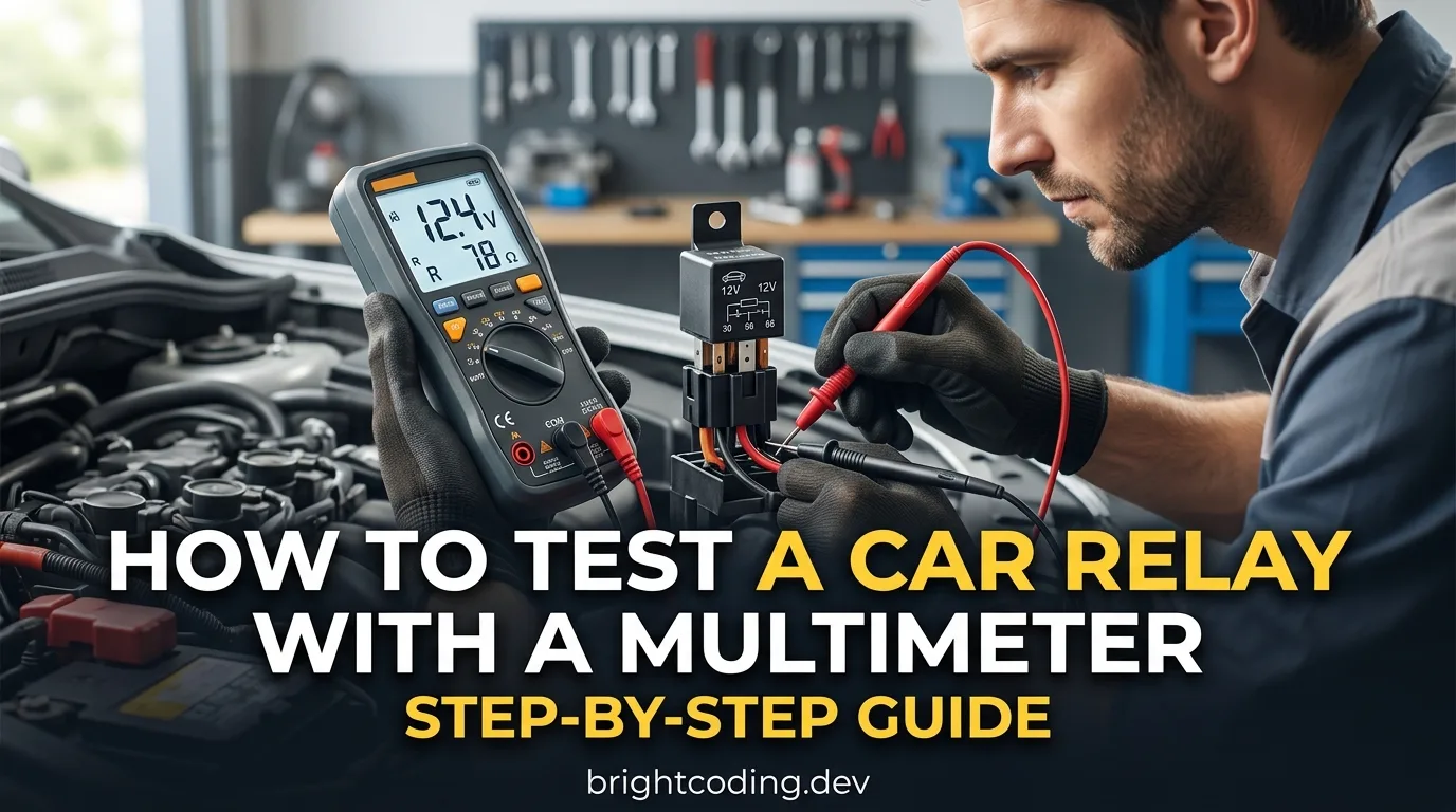
How to Test a Car Relay With a Multimeter: Step-by-Step Guide
A relay is one of the cheapest parts in your car and one of the most common reasons a fan, fuel pump, horn or headlight stops working. By the end of this guide you will be able to pull a suspect relay, test it on the bench with a multimeter, and know for certain whether it is dead or fine. Plan on…
Read the article →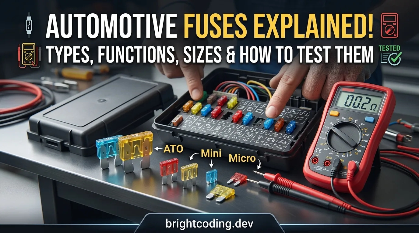
Automotive Fuses Explained: Types, Functions, Sizes, and How to Test Them
A blown fuse is one of the few car problems you can diagnose completely on your own, with a tool that costs less than a coffee. By the end of this guide you will know what fuses actually do, how to tell the different types and sizes apart, how to test one in under a minute, and how to replace it sa…
Read the article →
10 Hidden Features in Your Car That Dealerships Rarely Explain
Most of the useful stuff in your car is buried in the owner's manual, and nobody reads the owner's manual. Not the salesperson, not the service advisor, and probably not you. That is fine. I am going to walk you through the features that actually change how you live with a car, the ones that make y…
Read the article →
Diesel Engine: 10 Mistakes Drivers Make Without Knowing It
Diesel engines are tough, and that toughness fools people. A petrol car will often complain loudly when you treat it badly. A diesel just keeps going, quietly accumulating damage until the day it doesn't. That gap between "running fine" and "facing a four-figure repair bill" is where most owners lo…
Read the article →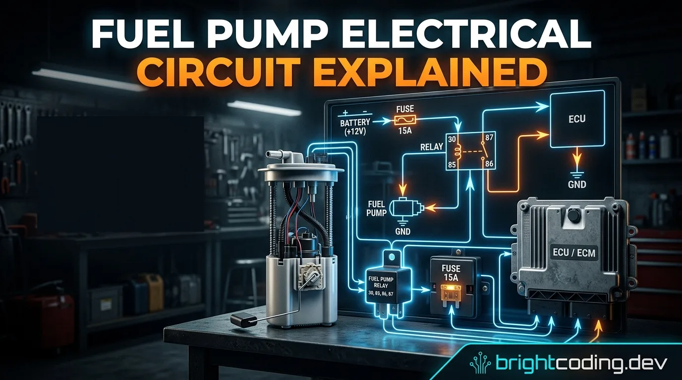
Fuel Pump Electrical Circuit Explained: Wiring Diagram, Relay, Fuse, ECU & Troubleshooting
Fuel pump electrical circuit explained: wiring diagram, relay, fuse, ECU control, priming, voltage drop, and troubleshooting. Learn how to diagnose no-power and no-start fuel pump problems before replacing parts.
Read the article →