Fuel Pump Electrical Circuit Explained: Wiring Diagram, Relay, Fuse, ECU & Troubleshooting
Fuel pump electrical circuit explained: wiring diagram, relay, fuse, ECU control, priming, voltage drop, and troubleshooting. Learn how to diagnose no-power and no-start fuel pump problems before replacing parts.
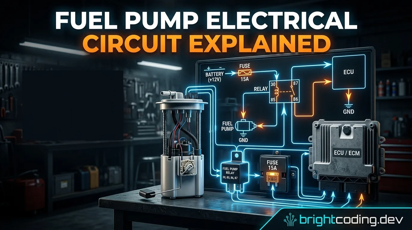
How Does a Fuel Pump Electrical Circuit Work?
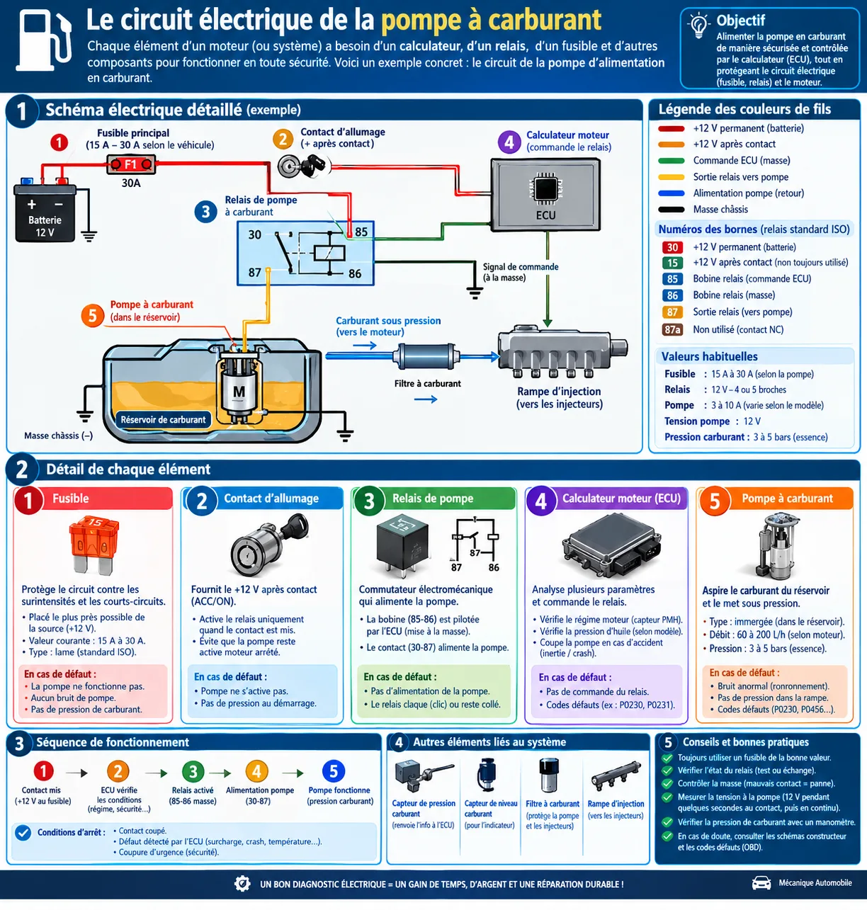
If you're diagnosing a fuel pump problem, you might assume the pump connects directly to the battery through a simple switch. In reality, modern fuel pump electrical circuits are far more sophisticated. A typical system includes multiple components working together:
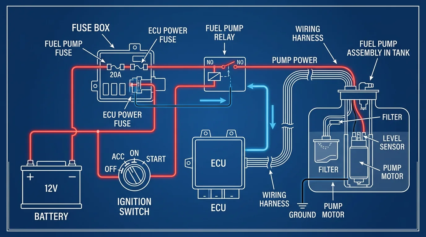
- Battery – Power source
- Fuse – Circuit protection
- Ignition switch – Activation signal
- Fuel pump relay – High-current switching
- Engine Control Unit (ECU) – Electronic management
- Fuel pump – The actual load
- Wiring harness – Power delivery
- Electrical connectors – Connection points
- Ground connections – Circuit completion
- Sensors and safety systems – Operating parameters
- Fuel pump control module – On some modern vehicles
The electrical circuit must deliver sufficient power to the fuel pump while allowing the vehicle's electronic control system to control and protect its operation. This article provides a complete technical breakdown of how these systems work, how to read wiring diagrams, and how to diagnose common faults.
1. What Is a Fuel Pump Electrical Circuit?
1.1 Definition
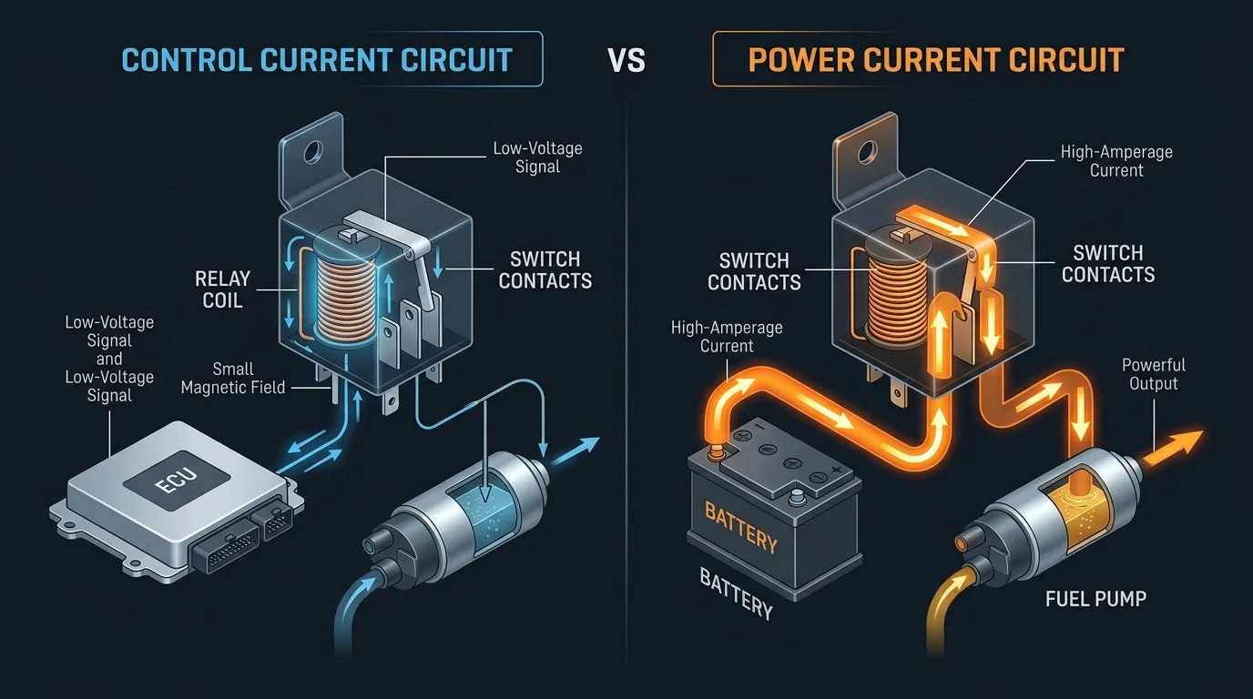
A fuel pump electrical circuit is the complete network of electrical components that supplies power to the fuel pump and controls when it operates. Modern vehicles use electrical control rather than simply connecting the pump directly to the battery because:
- The ECU needs to control when the pump runs for safety
- The pump draws significant current that requires relay or module control
- Safety systems must be able to cut fuel delivery in certain conditions
- Priming sequences improve starting performance
1.2 Main Functions
The fuel pump electrical circuit serves several critical functions:
- Supply electrical power to the pump motor
- Protect the circuit from excessive current
- Control when the pump operates based on engine conditions
- Establish the required fuel pressure for injection
- Stop the pump when operating conditions require it
- Integrate the pump into the vehicle's safety and engine-management systems
1.3 Why Can't the ECU Usually Power the Pump Directly?
This is a fundamental concept for understanding fuel pump circuits:
Control Current Path:
ECU → Relay Coil/Module (low current, typically 150-500mA)
Power Current Path:
Battery → Fuse → Relay/Module → Fuel Pump (high current, typically 5-15 amps)
The ECU cannot directly power the fuel pump because:
- Current limitations – ECU output drivers typically handle less than 1 amp
- Heat generation – High current would damage ECU internal circuits
- Voltage drop – Small ECU wiring would cause excessive voltage loss
- Cost – High-current drivers in the ECU would be expensive
The relay acts as an electrical amplifier, using a small control current to switch a much larger power current.
2. Main Components of a Fuel Pump Electrical Circuit
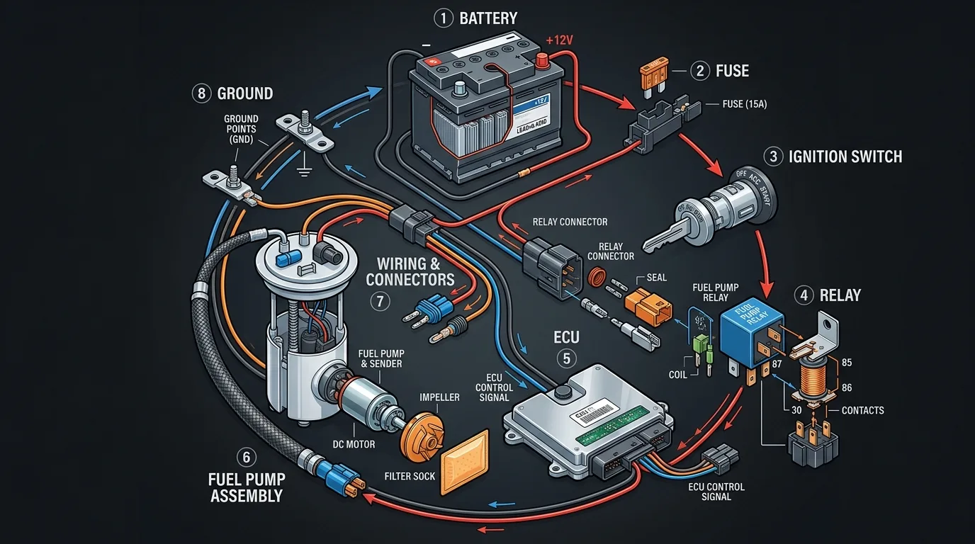
2.1 Battery
The battery serves as the primary source of electrical energy for the entire vehicle system.
Key characteristics:
- Typical passenger vehicle: 12V nominal (12.6V at rest, 13.5-14.5V with alternator running)
- Provides permanent positive supply to the fuse box
- Must maintain adequate voltage for proper pump operation
- Low battery voltage directly affects pump performance
2.2 Fuse
The fuse is the primary circuit protection device.
Functions:
- Overcurrent protection – Opens when current exceeds rating
- Short-circuit protection – Prevents wiring damage
- Circuit isolation – Allows safe disconnection for service
Critical warning: Never install a larger fuse than specified. The fuse is sized to protect the wiring, not just the pump. An oversized fuse may allow wiring to overheat and cause a fire before the fuse blows.
2.3 Ignition Switch
The ignition switch initiates the fuel pump activation sequence.
Typical positions:
| Position | Function |
|---|---|
| OFF | Everything disabled |
| ACC | Accessories only, pump off |
| ON | Ignition on, pump priming may occur |
| START | Cranking, pump runs continuously |
2.4 Fuel Pump Relay
The relay allows a relatively low-current control circuit to operate a higher-current load.
Relay components:
- Coil – Creates electromagnetic field when energized
- Electromagnetic field – Pulls armature to close contacts
- Internal contacts – Carry the high current to the pump
- Power circuit – Battery to pump through contacts
- Control circuit – ECU/ignition to coil
2.5 Engine Control Unit (ECU)
The ECU determines when fuel pump operation is permitted based on the vehicle's control strategy.
Typical ECU inputs for fuel pump control:
- Engine speed (RPM)
- Crankshaft position sensor
- Immobilizer authorization
- Ignition status
- Engine operating conditions
- Safety-related information (crash sensors)
2.6 Fuel Pump
The fuel pump itself is an electric motor driving a pumping mechanism.
Pump types:
- In-tank pumps – Most common, submerged in fuel for cooling
- Inline pumps – Mounted externally in the fuel line
- Fuel pump assemblies – Complete unit with pump, sender, and regulator
Components:
- Electric motor
- Pump mechanism (roller vane, turbine, or gear)
- Fuel pickup
- Check valve (maintains rest pressure)
2.7 Wiring and Connectors
Wiring is critical for proper pump operation.
Critical factors:
- Positive supply – Must handle full pump current
- Ground – Must provide low-resistance return path
- Connector resistance – Corroded terminals increase resistance
- Corrosion – Common in areas exposed to moisture
- Broken wires – Can cause intermittent operation
- Loose terminals – Create resistance and heat
- Voltage drop – Reduces voltage available at pump
2.8 Ground Connection
The ground completes the electrical circuit.
Consequences of poor ground:
- Low pump voltage
- Reduced pump performance
- Intermittent operation
- Excessive connector heating
- Starting problems
- Pump failure
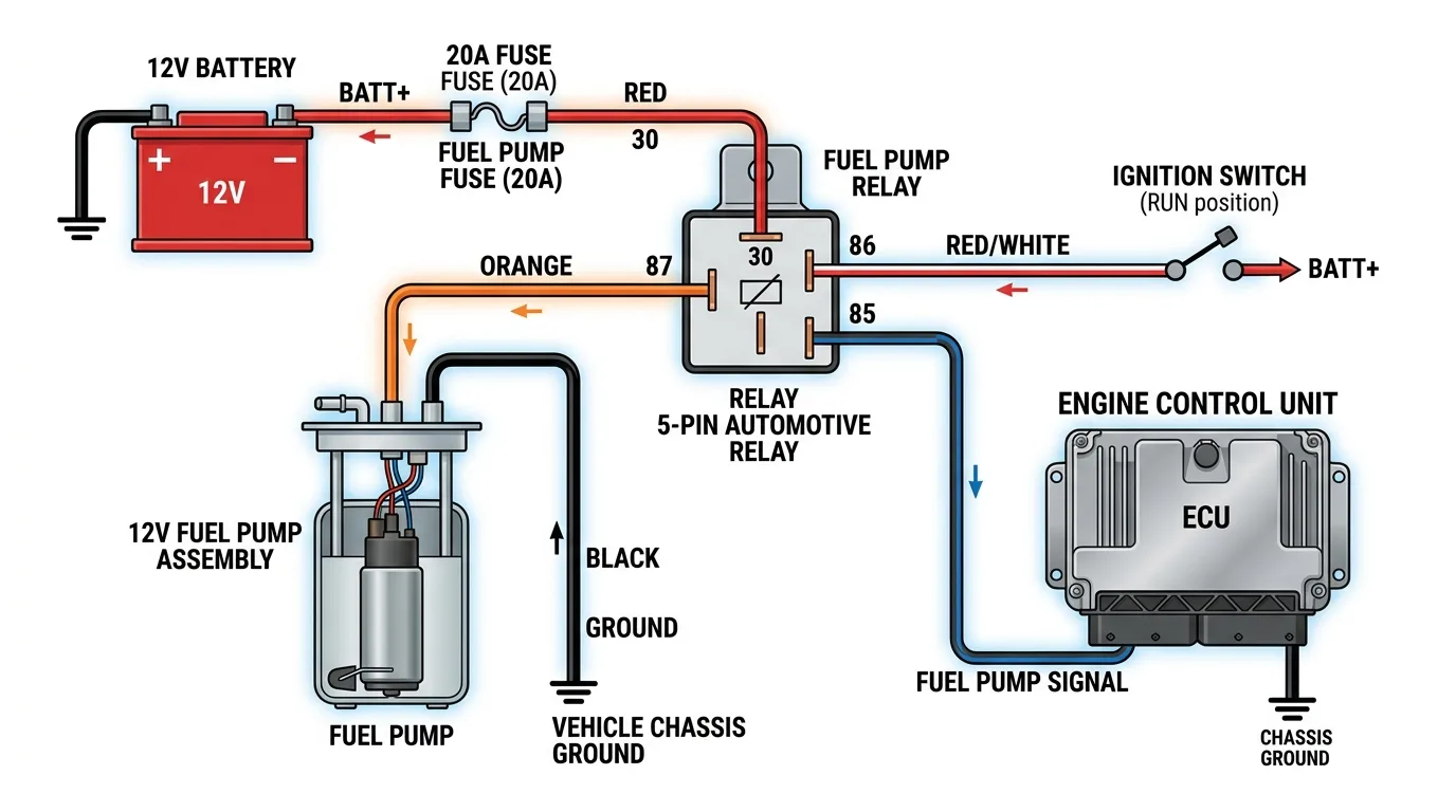
3. Understanding the Fuel Pump Wiring Diagram
3.1 How to Read an Automotive Wiring Diagram
Automotive wiring diagrams use standard symbols:
| Symbol | Component |
|---|---|
| ─── | Wire/Conductor |
| ⊥ | Ground |
| ═══ | Fuse |
| ▭ | Resistor |
| ( ) | Connector |
| ⚡ | Relay coil |
| ╱ | Switch |
3.2 The Power Circuit
The basic high-current path:
Battery (+) → Fuse → Relay Terminal 30 → Relay Terminal 87 → Fuel Pump → Ground
This is the high-current portion of the circuit that actually powers the pump motor.
3.3 The Control Circuit
The low-current control path:
Ignition/ECU → Relay Coil (Terminals 85-86) → Ground
The ECU may control the relay by providing power or ground to the coil, depending on vehicle architecture.
3.4 Complete Circuit Flow
Power Circuit:
Battery (+)
    ↓
Fuse
    ↓
Relay terminal 30
    ↓
Relay contact 87
    ↓
Fuel Pump
    ↓
Ground 31
    ↓
Battery (-)
Control Circuit:
Ignition / ECU
    ↓
Relay terminals 85–86
    ↓
Relay activation
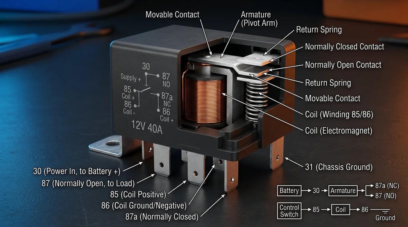
4. Understanding Automotive Relay Terminals
4.1 Terminal 30
The main battery-positive feed to the relay's power contacts. This terminal has power at all times (or when the ignition is on, depending on the circuit design).
4.2 Terminal 87
The switched output that supplies the load when the relay is activated. When the relay energizes, terminal 30 connects to terminal 87.
4.3 Terminal 85
One side of the relay coil. May be positive or ground depending on circuit design.
4.4 Terminal 86
The other side of the relay coil. The exact positive/ground arrangement of terminals 85 and 86 depends on the vehicle's circuit design.
4.5 Terminal 87a
The normally closed contact found on some 5-pin relays. This terminal has continuity with terminal 30 when the relay is NOT energized.
4.6 Terminal 31
The common automotive designation for electrical ground.
Important Note: Terminal numbering conventions are useful for understanding automotive circuits, but the actual vehicle wiring diagram should always be checked before testing or rewiring a circuit.
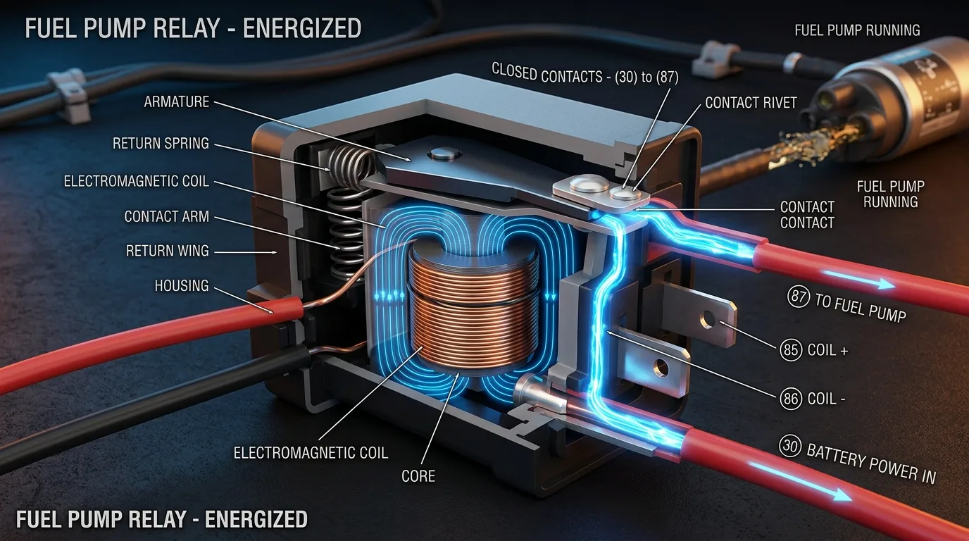
5. How the Fuel Pump Relay Works
5.1 Inside the Relay
A typical automotive relay contains:
- Coil – Copper wire wound around an iron core
- Electromagnetic field – Created when current flows through coil
- Armature – Movable metal piece pulled by magnetic field
- Contacts – Carry the high current
- Normally open contact – Open when relay is off
- Normally closed contact – Closed when relay is off (5-pin relays)
5.2 Control Circuit vs Power Circuit
| Circuit | Function |
|---|---|
| Control circuit | Activates the relay (low current) |
| Power circuit | Supplies current to the fuel pump (high current) |
| ECU signal | Determines when the relay should operate |
| Ground | Completes the electrical circuit |
5.3 What Happens When the Relay Is Activated?
Step-by-step sequence:
- The vehicle requests fuel pump operation
- The relay coil is energized
- The magnetic field moves the relay contact
- Terminal 30 connects to terminal 87
- Battery voltage reaches the fuel pump
- The pump starts operating
5.4 Symptoms of a Bad Relay
- No pump operation
- Intermittent starting
- Engine stalling
- Relay clicking without proper power delivery
- Voltage drop across relay contacts
- Overheating relay
- Burned contacts
Important point: A relay clicking does not automatically mean that the relay is electrically healthy. The contacts may be burned and unable to carry current even though the coil is functioning.
6. The Fuel Pump Fuse Explained
6.1 Why Is the Fuse Necessary?
The fuse protects:
- Wiring from overheating
- Relay contacts from damage
- Connectors from melting
- Fuel pump circuit from short circuits
6.2 What Happens When a Fuse Blows?
An open fuse interrupts the electrical supply, preventing:
- Further circuit damage
- Fire risk from overheated wiring
- Damage to the fuel pump
6.3 Why Does a Fuel Pump Fuse Keep Blowing?
Possible causes:
- Short circuit in wiring
- Damaged wiring (chafed against metal)
- Failed fuel pump (internal short)
- Excessive pump current draw
- Corroded connector causing resistance
- Mechanical pump problem causing excessive electrical load
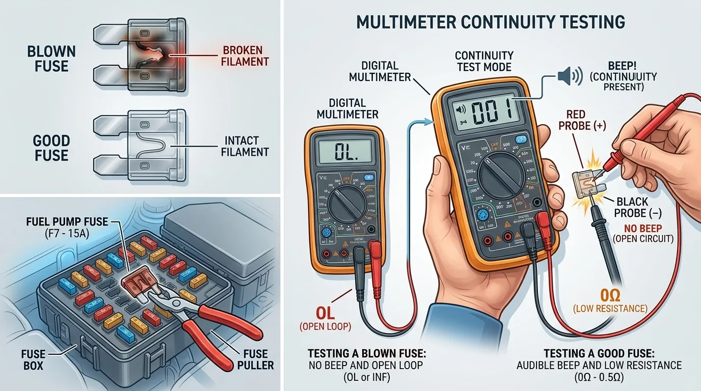
6.4 How to Test the Fuse
Testing methods:
- Visual inspection – Look for broken element
- Continuity testing – Use multimeter to check for continuity
- Voltage testing – Check for power on both sides of fuse
Critical reminder: Always replace with the correct fuse rating. Never substitute a higher-rated fuse.
7. How the ECU Controls the Fuel Pump
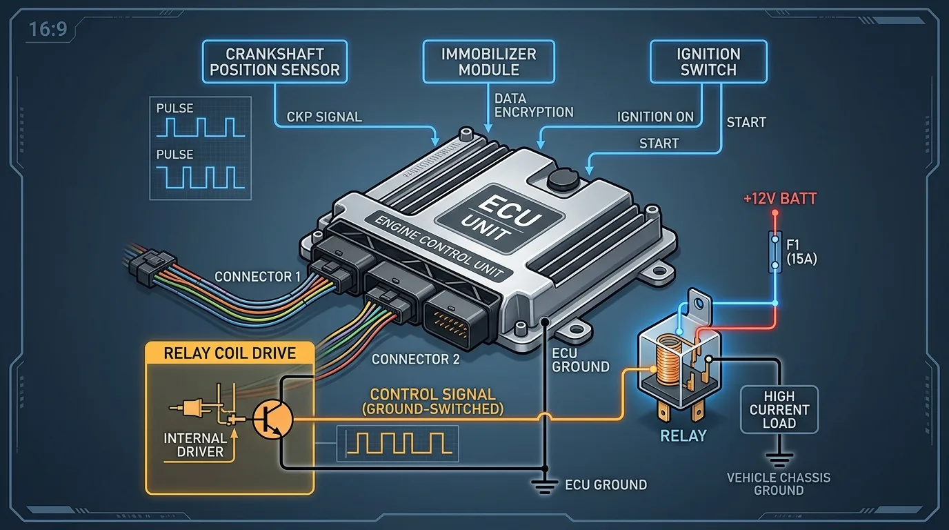
7.1 What Is the ECU?
The Engine Control Unit is the electronic control system responsible for managing many engine functions, including fuel delivery.
7.2 ECU Inputs Related to Fuel Pump Operation
Depending on the vehicle:
- Crankshaft position sensor (engine speed)
- Camshaft position sensor
- Engine speed (RPM)
- Ignition status
- Immobilizer status
- Engine operating conditions
- Crash/safety information
- Fuel pressure information
7.3 ECU Output
The ECU can control:
- Fuel pump relay
- Fuel pump control module
- Pump speed command (variable voltage or PWM)
7.4 ECU Ground-Side Control
A common concept is the ECU controlling a relay by switching the control circuit toward ground:
Battery → Relay Coil → ECU → Ground
In this configuration:
- One side of the relay coil has constant power
- The ECU provides the ground path to energize the relay
- This is called "ground-side switching"
7.5 ECU Protection Strategy
The ECU may stop pump operation when conditions require it:
- Ignition OFF
- Engine not running (no RPM signal)
- Loss of required engine-speed information
- Immobilizer authorization failure
- Safety event (crash detected)
- Detected system fault
8. Fuel Pump Priming: Why Does the Pump Run for a Few Seconds?
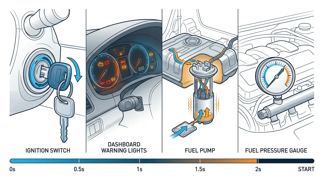
This is a common question from vehicle owners.
Typical priming sequence:
| Step | Action |
|---|---|
| 1 | Driver switches ignition ON |
| 2 | The control system wakes up |
| 3 | The ECU/module requests pump operation |
| 4 | The relay/module powers the pump |
| 5 | The pump builds fuel pressure |
| 6 | The system determines whether continued operation is required |
Why priming matters:
- Ensures fuel pressure is available for quick starting
- Compensates for fuel pressure loss during sitting
- Improves cold-start performance
Note: The exact priming time and control strategy vary by vehicle. Some vehicles prime for 2 seconds, others for 5 seconds, and some only prime when cranking.
9. How the Fuel Pump Supplies the Engine
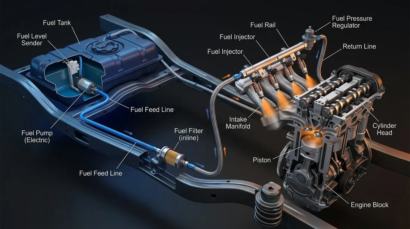
Fuel path:
Fuel Tank
    ↓
Fuel Pump
    ↓
Fuel Filter
    ↓
Fuel Line
    ↓
Fuel Rail
    ↓
Fuel Injectors
    ↓
Engine
Critical distinction:
The electrical circuit powers and controls the pump, while the fuel circuit transports and pressurizes the fuel. These are two separate systems that work together.
10. Fuel Pump Voltage, Current, Flow and Pressure
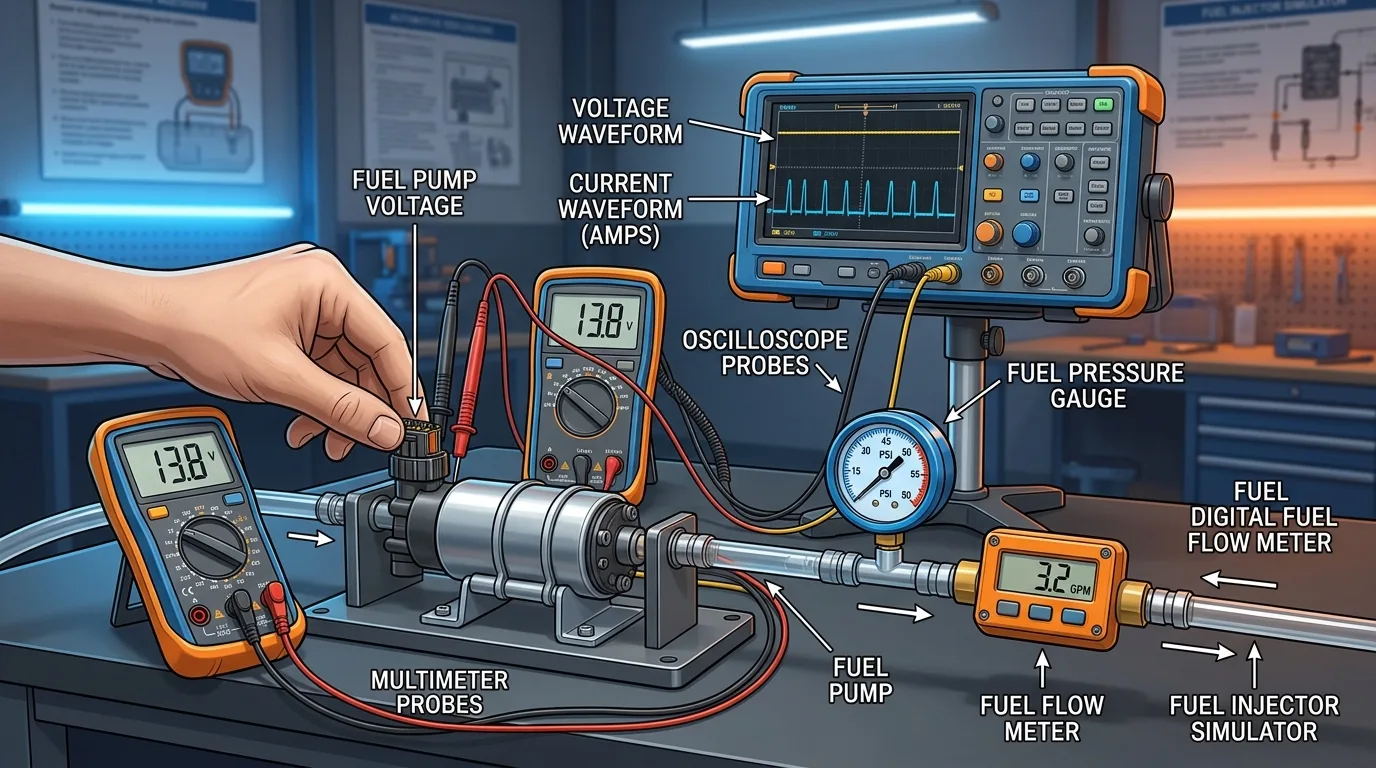
10.1 Pump Voltage
Correct voltage is essential for proper pump operation. Low voltage causes:
- Reduced pump speed
- Lower fuel pressure
- Reduced flow rate
- Potential engine performance issues
10.2 Pump Current
Excessive current can indicate:
- Pump wear (increased friction)
- Mechanical resistance
- Internal electrical problems
- Restricted fuel flow
10.3 Fuel Flow
Pressure alone does not always tell the complete story. A pump can produce adequate pressure but insufficient volume (flow rate).
10.4 Fuel Pressure
- Required pressure varies by vehicle
- Manufacturer specifications should always be used
- Different injection systems require different pressures
- Never assume one universal pressure value applies to every vehicle
11. Fuel Pump Electrical Circuit Troubleshooting
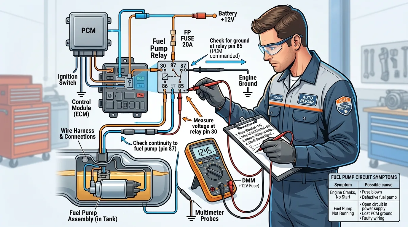
11.1 Common Symptoms
| Symptom | Possible Cause |
|---|---|
| Pump completely silent | Fuse, relay, wiring, ground, pump or control issue |
| No-start | Fuel pressure or electrical supply problem |
| Intermittent starting | Relay, connector, wiring or pump fault |
| Pump runs continuously | Relay/control circuit problem |
| Fuse keeps blowing | Short circuit or excessive current |
| Low fuel pressure | Pump, filter, regulator or electrical supply problem |
| Pump gets noisy | Pump wear, fuel starvation or other mechanical issue |
12. Step-by-Step Fuel Pump Electrical Diagnosis
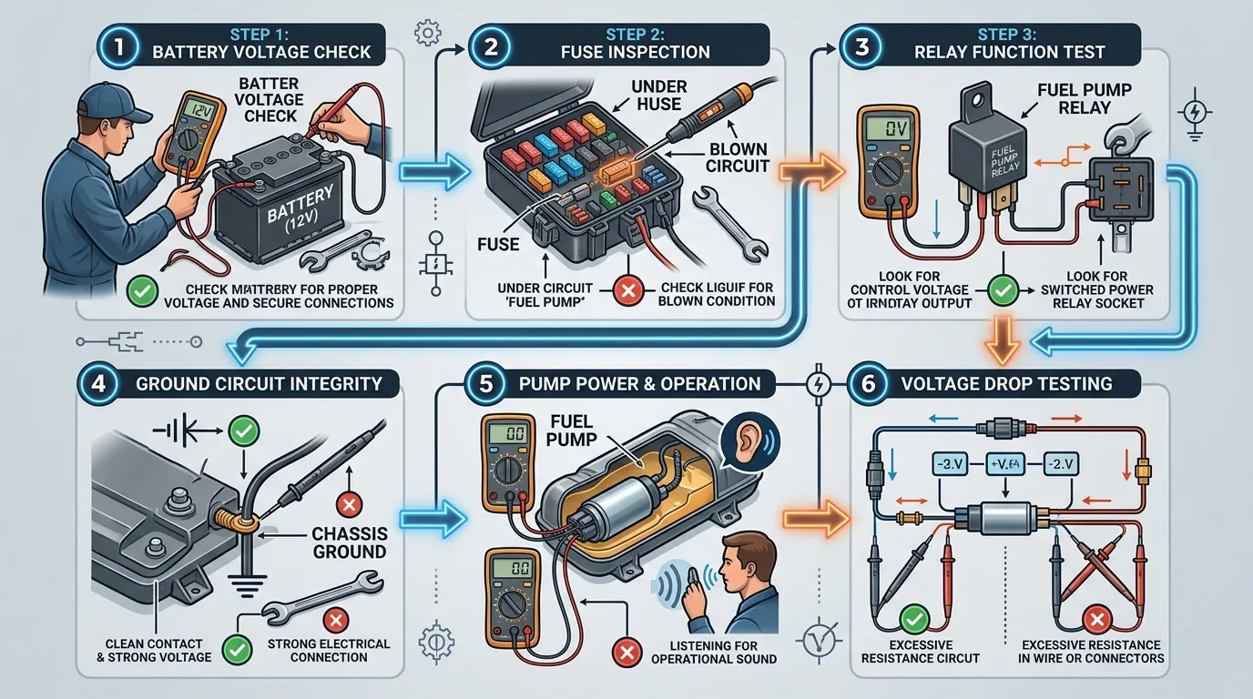
Step 1 — Check the Battery
Verify that the electrical system has sufficient voltage (12.6V at rest minimum).
Step 2 — Check the Fuel Pump Fuse
Confirm:
- Correct fuse rating
- Continuity through fuse
- Voltage supply to fuse
Step 3 — Check the Relay
Test:
- Coil resistance
- Power input at terminal 30
- Switched output at terminal 87
- Control signal at terminals 85/86
Step 4 — Check the Ground
Inspect:
- Ground point condition
- Ground cable integrity
- Connector condition
- Corrosion
- Voltage drop
Step 5 — Check Voltage at the Pump
Measure the voltage at the fuel pump connector while the pump is commanded ON. Compare to battery voltage.
Step 6 — Check Voltage Drop
Voltage drop testing can reveal resistance that a simple open-circuit voltage measurement may miss. Test both the power and ground sides of the circuit under load.
Step 7 — Check Pump Current
Compare measured current with the manufacturer's specification using a current clamp or series ammeter.
Step 8 — Check Fuel Pressure
Use the correct pressure-testing procedure for the vehicle. Check both pressure and volume.
Step 9 — Scan for Diagnostic Trouble Codes
Use an appropriate scan tool and consult vehicle-specific service information.
13. How to Diagnose a Fuel Pump That Has No Power
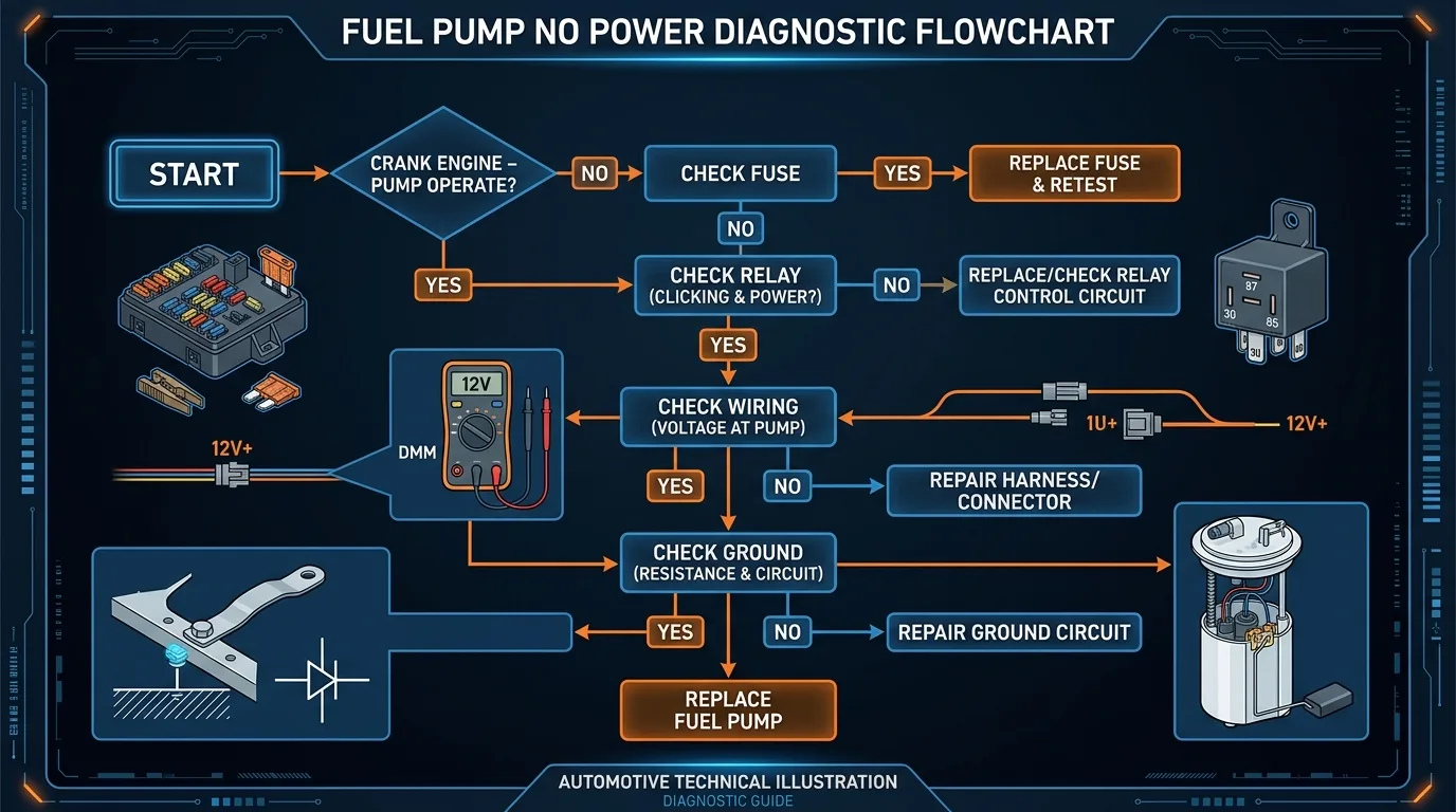
Diagnostic flowchart:
Fuel pump not running
    ↓
Check fuse
    → Fuse blown → Find cause
    → Fuse OK → Continue
    ↓
Check relay
    → Relay not commanded → Check ECU/control circuit
    → Relay commanded → Continue
    ↓
Check relay output
    → No output → Relay/contact problem
    → Output OK → Continue
    ↓
Check wiring
    → Voltage lost → Wiring/connector problem
    → Voltage present → Continue
    ↓
Check ground
    → Poor ground → Repair ground
    → Ground OK → Continue
    ↓
Check pump
    → Pump does not operate → Pump/assembly fault
14. Fuel Pump Electrical Fault Codes
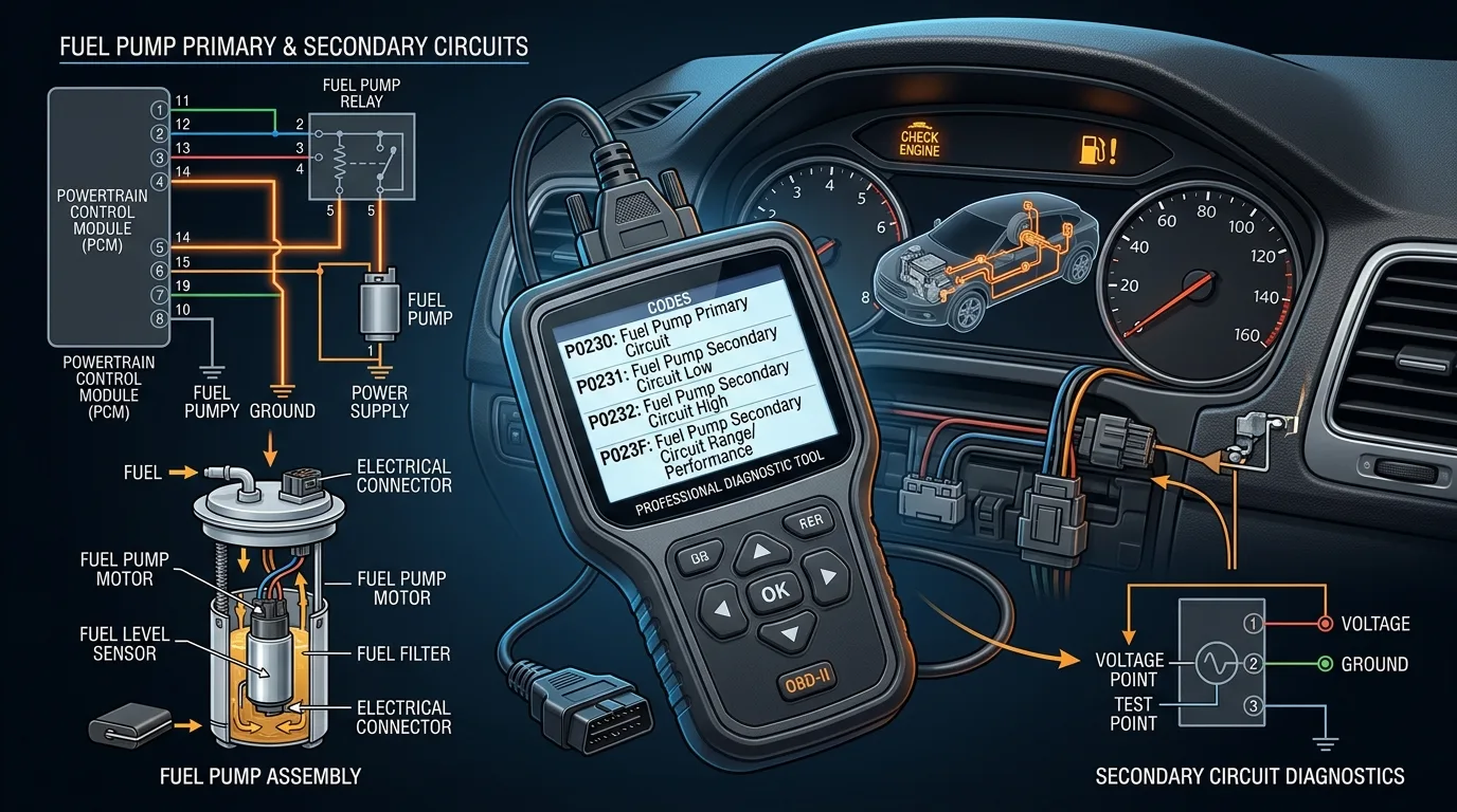
Common generic OBD-II fuel-pump-related codes:
| Code | Description |
|---|---|
| P0230 | Fuel Pump Primary Circuit |
| P0231 | Fuel Pump Secondary Circuit Low |
| P0232 | Fuel Pump Secondary Circuit High |
| P023F | Fuel Pump Secondary Circuit |
Important: OBD-II code descriptions and diagnostic procedures can vary by manufacturer. Always consult vehicle-specific service information.
15. Fuel Pump Relay vs Fuel Pump Control Module
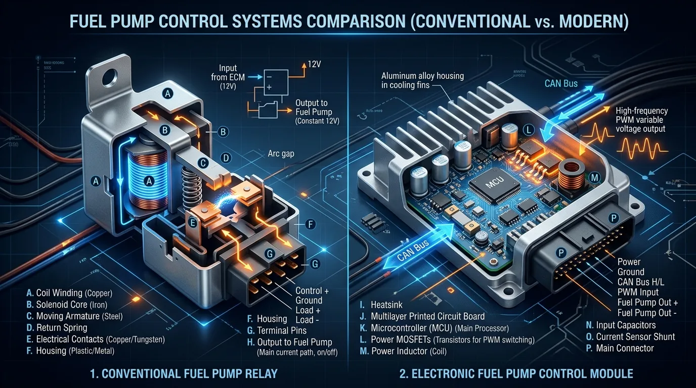
| Feature | Conventional Relay | Fuel Pump Control Module |
|---|---|---|
| Technology | Electromechanical | Electronic |
| Basic function | ON/OFF switching | Electronic pump control |
| Pump speed control | Usually limited | May allow variable control |
| ECU communication | Usually simple command | May involve communication/network signals |
| Diagnostic complexity | Lower | Higher |
| Typical applications | Conventional systems | Many modern vehicles |
Modern systems can use a dedicated module instead of a simple relay, allowing variable pump speed control for improved efficiency and reduced noise.
16. Common Fuel Pump Circuit Failures
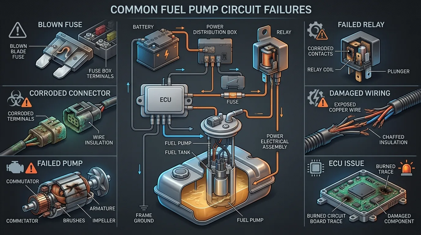
16.1 Blown Fuse
Symptoms: No pump operation Causes: Short circuit, overload Tests: Visual, continuity Repair: Replace fuse, find root cause
16.2 Failed Relay
Symptoms: No pump operation, intermittent operation Causes: Burned contacts, open coil Tests: Coil resistance, contact continuity Repair: Replace relay
16.3 Poor Ground
Symptoms: Low pump voltage, weak operation Causes: Corrosion, loose connection Tests: Voltage drop test Repair: Clean and tighten ground
16.4 Corroded Connector
Symptoms: Intermittent operation, voltage drop Causes: Moisture intrusion, age Tests: Visual, voltage drop Repair: Clean or replace connector
16.5 Damaged Wiring
Symptoms: Intermittent or no operation Causes: Chafing, rodent damage, heat Tests: Visual, continuity Repair: Repair or replace wiring
16.6 Failed Fuel Pump
Symptoms: No operation, low pressure Causes: Wear, contamination, electrical failure Tests: Voltage, current, pressure Repair: Replace pump
16.7 ECU Command Missing
Symptoms: No relay activation Causes: Sensor failure, immobilizer issue Tests: Scan tool, signal verification Repair: Diagnose ECU inputs
16.8 Immobilizer Authorization Problem
Symptoms: No start, no pump prime Causes: Key/immobilizer mismatch Tests: Scan tool, security light Repair: Relearn keys, repair immobilizer
16.9 Fuel Pump Control Module Failure
Symptoms: No operation, codes present Causes: Electronic failure, overheating Tests: Scan tool, output verification Repair: Replace module
16.10 Excessive Voltage Drop
Symptoms: Weak pump operation Causes: Resistance in circuit Tests: Voltage drop testing Repair: Repair high-resistance points
17. Safety When Working on a Fuel Pump Circuit
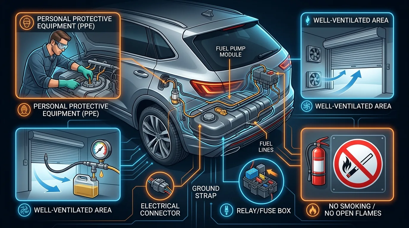
⚠️ WARNING: Fuel is highly flammable. Follow all safety precautions.
- Work in a well-ventilated area
- Keep sparks and flames away
- Do not smoke
- Use appropriate protective equipment
- Follow the manufacturer's fuel-system depressurization procedure
- Avoid short circuits
- Never install an oversized fuse
- Use appropriate electrical test equipment
- Follow special procedures for high-pressure gasoline direct injection
- Follow special procedures for high-pressure diesel common-rail systems
18. Fuel Pump Circuit vs Fuel Injection Circuit
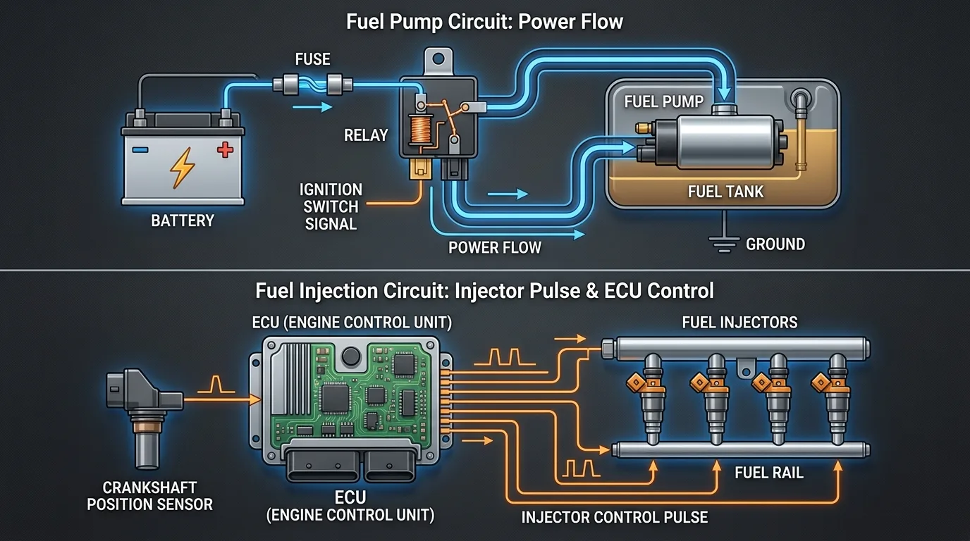
| System | Responsibility |
|---|---|
| Fuel Pump Circuit | Power → Pump → Fuel pressure/flow |
| Fuel Injection Control | ECU → Injectors → Injection timing and quantity |
The fuel pump circuit provides the pressure and volume, while the injection circuit controls when and how much fuel enters the engine.
19. Gasoline vs Diesel Fuel Pump Electrical Systems
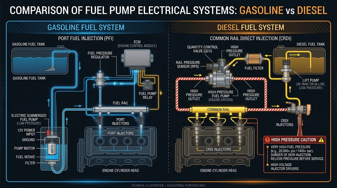
| Feature | Gasoline | Diesel |
|---|---|---|
| Low-pressure fuel supply | Common | Common |
| High-pressure system | Depends on injection type | Common in modern common-rail systems |
| Electric pump | Common in many vehicles | Architecture varies |
| Injection pressure | Depends on system | Very high in common rail |
| Safety considerations | Important | Especially important around high-pressure components |
Diesel warning: Diesel common-rail systems require particular caution because high-pressure fuel can cause serious injury.
20. Frequently Asked Questions
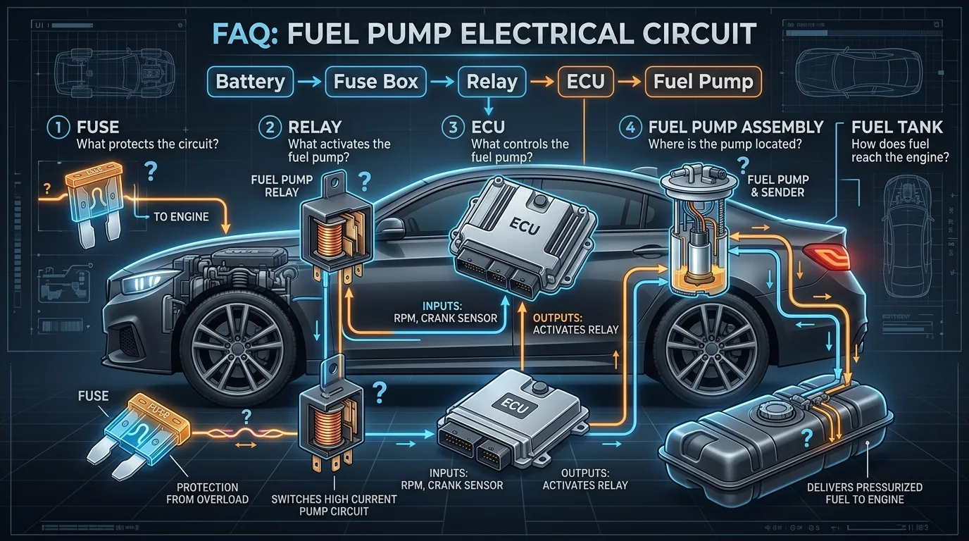
Q: What does a fuel pump relay do? A: It uses a low-current control signal to switch high current to the fuel pump.
Q: What do terminals 30, 85, 86 and 87 mean? A: 30 = power input, 87 = power output, 85/86 = relay coil terminals.
Q: Does the ECU directly power the fuel pump? A: No, the ECU controls a relay or module which then powers the pump.
Q: Why does the fuel pump run when I turn the key on? A: This is the priming sequence to build fuel pressure for starting.
Q: Why does my fuel pump have no power? A: Could be fuse, relay, wiring, ground, or control issue.
Q: Why does my fuel pump fuse keep blowing? A: Usually indicates a short circuit or excessive current draw.
Q: Can a bad relay cause a no-start condition? A: Yes, if the relay doesn't close, the pump won't receive power.
Q: Can a bad ground cause low fuel pressure? A: Yes, poor ground causes voltage drop and reduced pump performance.
Q: How do I test a fuel pump with a multimeter? A: Check voltage at pump connector, check resistance of pump motor.
Q: How do I test a fuel pump relay? A: Test coil resistance, check for power at terminals, test contact continuity.
Q: What voltage should reach the fuel pump? A: Within 0.5V of battery voltage is typical.
Q: How can I tell if the ECU is commanding the fuel pump? A: Use a scan tool to view live data, or test relay control circuit.
Q: What is the difference between a fuel pump relay and a fuel pump control module? A: A relay is ON/OFF; a module can provide variable control.
Q: Can an immobilizer disable the fuel pump? A: Yes, many vehicles cut fuel pump operation when immobilizer is active.
Q: Can a weak battery affect fuel pump operation? A: Yes, low voltage reduces pump speed and pressure.
21. Final Diagnostic Checklist
Fuel Pump Electrical Diagnostic Checklist
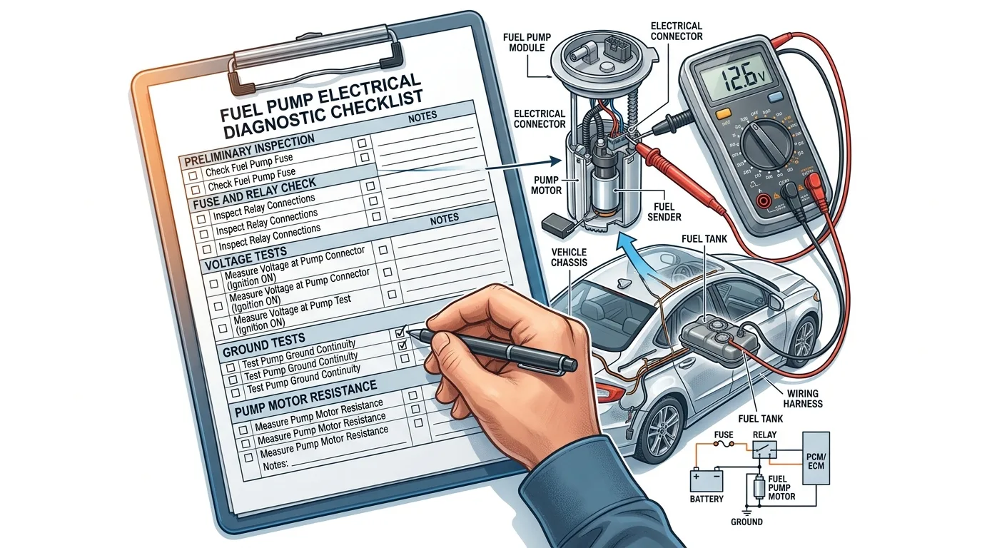
- ☐ Battery voltage checked
- ☐ Correct fuel pump fuse identified
- ☐ Fuse tested
- ☐ Relay identified
- ☐ Relay power supply checked
- ☐ Relay command checked
- ☐ Relay output checked
- ☐ Fuel pump connector inspected
- ☐ Pump voltage checked
- ☐ Pump ground checked
- ☐ Voltage drop tested
- ☐ Pump current checked
- ☐ Fuel pressure checked
- ☐ OBD-II codes scanned
- ☐ ECU command verified
- ☐ Wiring diagram compared with actual vehicle
- ☐ Manufacturer specifications checked
Conclusion
A fuel pump problem should not automatically be diagnosed as a failed fuel pump. The electrical circuit is a complete system where any component can cause the pump to stop working.
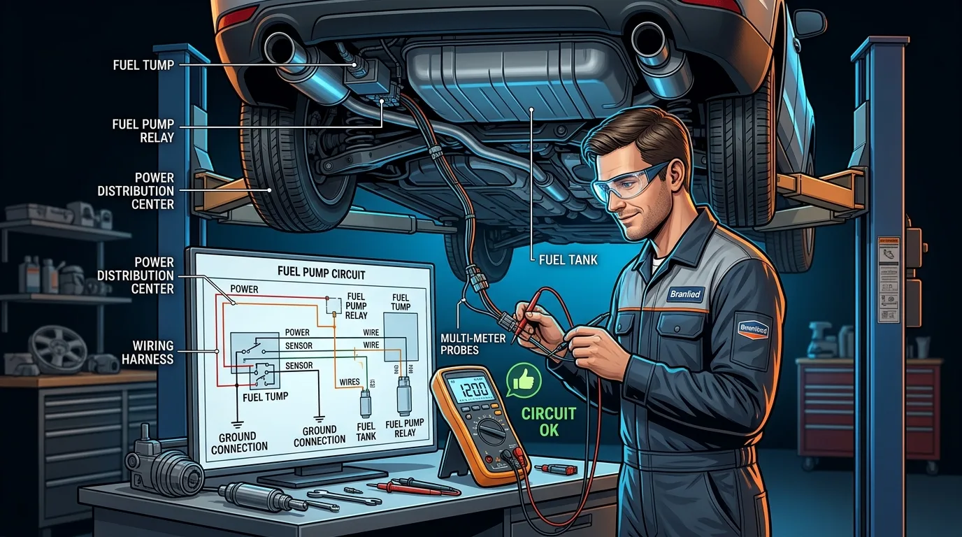
A proper diagnosis should determine whether the problem comes from:
Power → Fuse → Relay → Wiring → Ground → ECU Command → Pump → Fuel Pressure
Remember the fundamental principle: Test before replacing parts. By following a systematic diagnostic approach, you can accurately identify the fault and avoid unnecessary repairs.
Summary
Related articles

10 Diesel Engine Maintenance Tips Every Owner Should Know
Diesel engines reward owners who pay attention. Treat yours well and it can run for hundreds of thousands of miles; neglect a few basics and you will be funding a very expensive repair.
Read the article →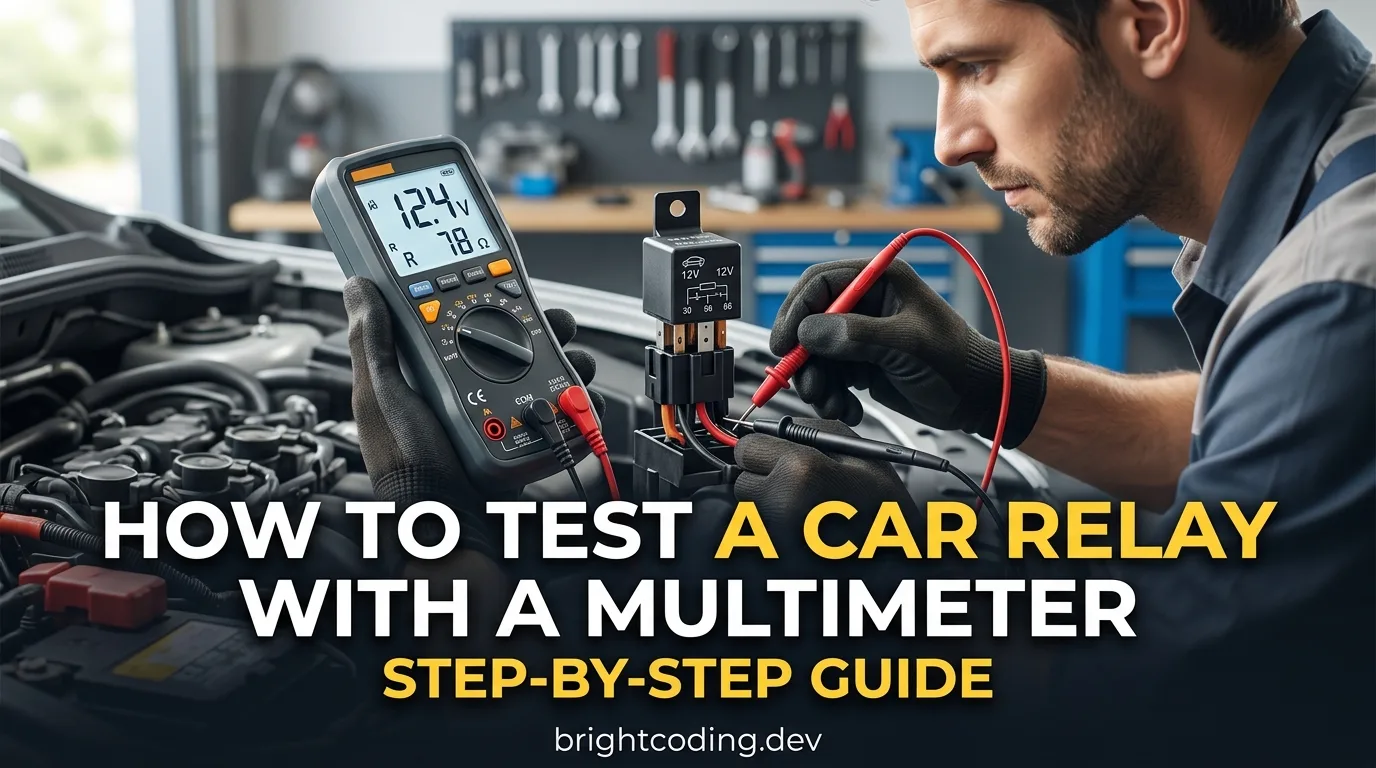
How to Test a Car Relay With a Multimeter: Step-by-Step Guide
A relay is one of the cheapest parts in your car and one of the most common reasons a fan, fuel pump, horn or headlight stops working. By the end of this guide you will be able to pull a suspect relay, test it on the bench with a multimeter, and know for certain whether it is dead or fine. Plan on…
Read the article →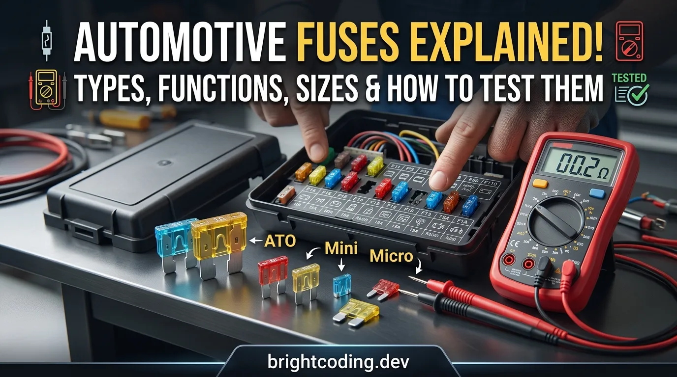
Automotive Fuses Explained: Types, Functions, Sizes, and How to Test Them
A blown fuse is one of the few car problems you can diagnose completely on your own, with a tool that costs less than a coffee. By the end of this guide you will know what fuses actually do, how to tell the different types and sizes apart, how to test one in under a minute, and how to replace it sa…
Read the article →
10 Hidden Features in Your Car That Dealerships Rarely Explain
Most of the useful stuff in your car is buried in the owner's manual, and nobody reads the owner's manual. Not the salesperson, not the service advisor, and probably not you. That is fine. I am going to walk you through the features that actually change how you live with a car, the ones that make y…
Read the article →
Diesel Engine: 10 Mistakes Drivers Make Without Knowing It
Diesel engines are tough, and that toughness fools people. A petrol car will often complain loudly when you treat it badly. A diesel just keeps going, quietly accumulating damage until the day it doesn't. That gap between "running fine" and "facing a four-figure repair bill" is where most owners lo…
Read the article →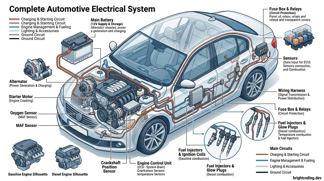
Understanding Automotive Electrical Systems: ECU, Sensors & Wiring
A complete guide to automotive electrical systems, covering batteries, alternators, starters, ECUs, sensors, actuators, wiring diagrams, diagnostics, safety, and the key differences between gasoline and diesel engine electrical systems.
Read the article →