Stop Throwing Parts at Your Car: The 4-Step Sensor Diagnostic Method That Actually Works
A fault code points to a circuit or behavior—not automatically a failed sensor. This practical guide covers the 8 engine sensors every DIYer and technician should understand, plus the 4-step test process that prevents expensive parts-swapping and misdiagnosis.
Your check engine light is on. The scanner says "O2 Sensor." You replace it. The light comes back. Sound familiar?
You're not alone—and you're not the problem. The problem is that a fault code tells you where to look, not what to replace. Professional technicians know this. Now you will too.
This guide breaks down the 8 critical engine sensors every DIYer and mechanic must understand, plus the universal 4-step diagnostic method that separates parts-swappers from actual diagnosticians.
The $200 Lesson Most Mechanics Learn the Hard Way
Here's the truth that auto parts stores don't want you to know: a P0130 code doesn't mean your O2 sensor is bad. It means the circuit is reporting something unexpected. The sensor itself might be fine. The wiring might be fine. The problem could be a vacuum leak, a failing fuel injector, or even a bad ground.
The difference between a $50 fix and a $500 misdiagnosis? Testing before replacing.
Let's build your diagnostic toolkit—one sensor at a time.
The Big 8: Engine Sensors That Control Everything
Before diving into individual sensors, understand the framework. Every diagnostic follows the same 4-step process:
| Step | Action | Tool |
|---|---|---|
| 1 | Visual inspection | Your eyes |
| 2 | Circuit verification | Multimeter |
| 3 | Signal analysis | Oscilloscope |
| 4 | Compare to reference | Scan tool + specs |
The Golden Rule: A fault code identifies a circuit or behavior—not a failed component. The sensor is the last suspect, not the first.
1. Crankshaft Position Sensor (CKP) — The Engine's Heartbeat
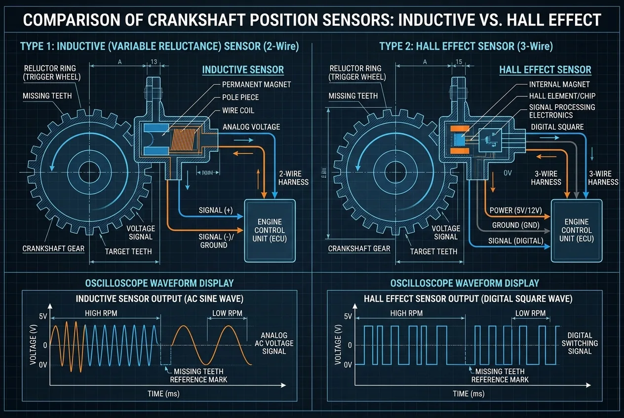
What it does: Measures crankshaft position and speed. Without this signal, the engine won't start. Period.
Two types you'll encounter:
| Type | Wires | Signal | Test Method |
|---|---|---|---|
| Inductive (passive) | 2 | AC voltage (generated by rotation) | Resistance + AC voltage during crank |
| Hall Effect (active) | 3 | Digital square wave | Power, ground, signal with connector attached |
Quick Test (Inductive):
- Ignition OFF, disconnect sensor
- Measure resistance across terminals—compare to manufacturer spec
- Reconnect, set multimeter to AC volts
- Crank engine—you should see 0.5V to several volts AC
Quick Test (Hall Effect):
- Key ON, backprobe the connector
- Verify power (often 5V or 12V) and ground
- Crank engine—signal should toggle between low and high
Common Codes: P0335–P0339
Don't Be Fooled: A bad CKP will prevent injection AND ignition. But so will a bad ECU power feed, a broken reluctor ring, or excessive air gap. Check those too.
Pro Tip: No RPM reading on your scan tool during cranking = CKP circuit problem. But verify power and ground at the sensor before condemning it.
2. Camshaft Position Sensor (CMP) — The Timing Referee
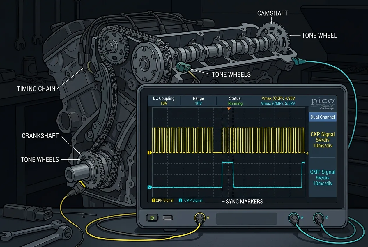
What it does: Tells the ECU which cylinder is on which stroke. Enables sequential injection and variable valve timing.
Why it matters: The CKP tells the engine when to fire. The CMP tells it which cylinder to fire. If they disagree, you get rough running, no-starts, or limp mode.
Testing Highlights:
- Hall-effect CMP: Verify 5V reference, ground, and toggling signal during crank
- Inductive CMP: Check AC voltage during crank, compare to CKP pattern
The Critical Comparison: On engines with both CKP and CMP, use a two-channel scope. Compare the signals. A jumped timing chain, a damaged reluctor wheel, or a failing VVT solenoid will show as signal misalignment—not necessarily a dead sensor.
Common Codes: P0340–P0349
Before Replacing:
- Check timing chain/belt alignment
- Inspect VVT phaser operation
- Verify oil condition (VVT is oil-driven)
- Examine reluctor wheel for damage
Pro Tip: CMP codes often appear alongside CKP codes when the real problem is timing. Don't replace both sensors—verify the mechanical timing first.
3. Mass Air Flow Sensor (MAF) — The Air Accountant
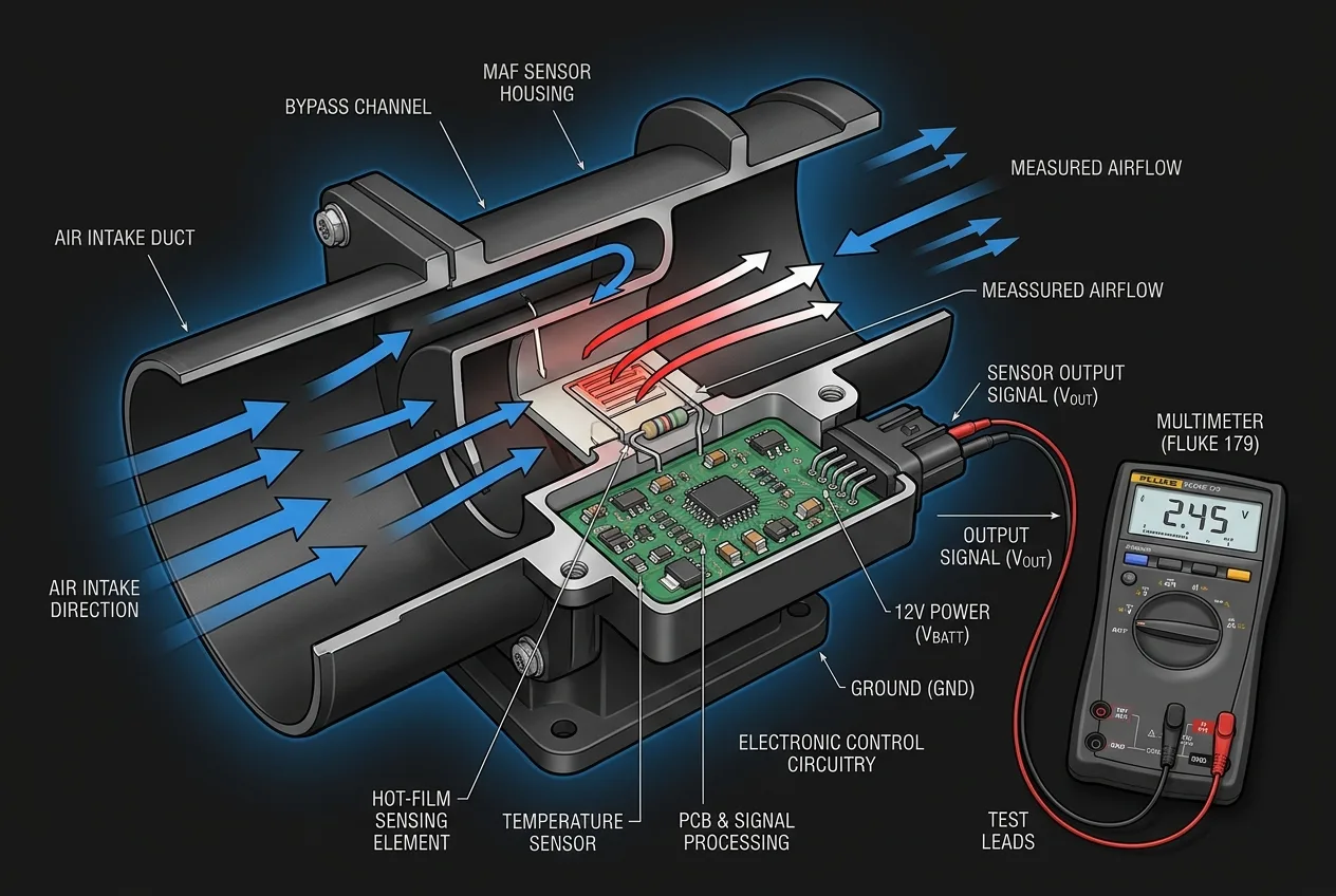
What it does: Measures the mass of air entering the engine. The ECU uses this to calculate fuel delivery.
Types:
- Analog voltage output (often 0.5–4.5V range)
- Frequency output (varies with airflow)
- Digital output (newer systems)
Testing Strategy:
- Scan tool first: Compare MAF reading (g/s) to expected values at idle and under load
- Multimeter: Verify power, ground, and signal voltage/frequency
- Oscilloscope: Watch for smooth signal variation during acceleration—look for dropouts or spikes
The Consistency Check: Cross-reference MAF data with:
- Engine RPM
- MAP sensor reading
- Calculated load
- Fuel trims
A MAF reporting low airflow (due to contamination) will cause lean fuel trims. A MAF reporting high airflow (due to a leak downstream) will cause rich trims.
Common Codes: P0100–P0104
Never Do This: Spray unknown cleaners directly on the sensing element. Use only MAF-specific cleaner, and let it dry completely.
Pro Tip: A dirty MAF often tests "within spec" on voltage but underreports airflow. Compare g/s readings to known-good values, not just voltage.
4. Manifold Absolute Pressure Sensor (MAP) — The Load Calculator
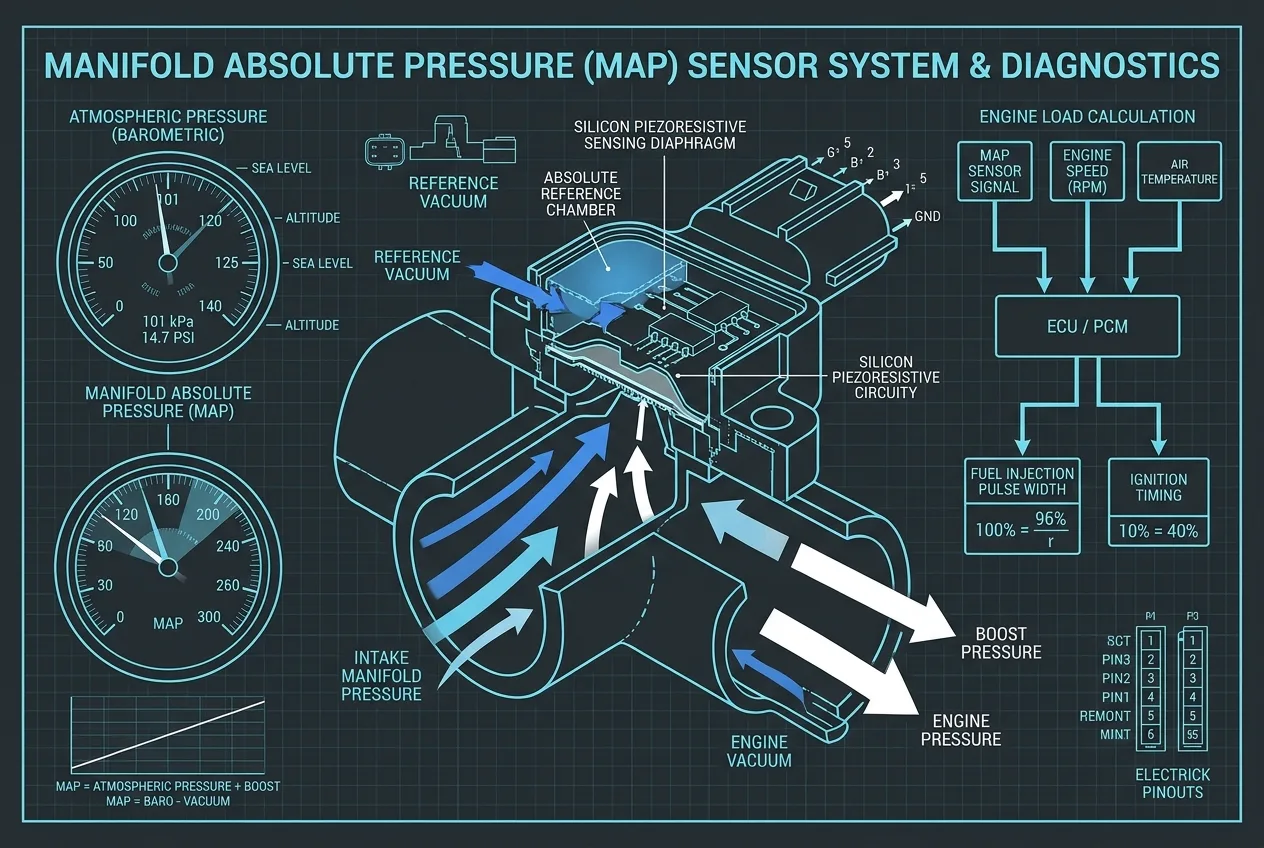
What it does: Measures absolute pressure in the intake manifold. The ECU uses this to estimate engine load and calculate fuel.
Key Distinction: MAP measures absolute pressure (reference: vacuum). Boost gauges measure relative pressure (reference: atmosphere). Don't confuse them.
Quick Verification:
- Key ON, engine OFF: MAP should read approximately barometric pressure (local atmospheric)
- Idle (naturally aspirated): MAP should be low (high vacuum)—typically 25–40 kPa
- Turbo boost: MAP exceeds atmospheric—verify against boost specifications
Testing Checklist:
- Compare MAP reading to actual atmospheric pressure (engine off)
- Check 5V reference and ground
- Measure signal voltage with backprobe
- Verify MAP responds to throttle changes (vacuum drops under acceleration)
Common Codes: P0105–P0109
Before Replacing:
- Check vacuum hoses for cracks or disconnection
- Inspect intake boot for leaks
- Verify intercooler piping (turbo vehicles)
- Test EGR operation—a stuck EGR valve skews MAP readings
Pro Tip: A MAP sensor reading atmospheric pressure at idle indicates a massive vacuum leak or a faulty sensor. Verify with a vacuum gauge before replacing.
5. Intake Air Temperature Sensor (IAT) — The Density Corrector
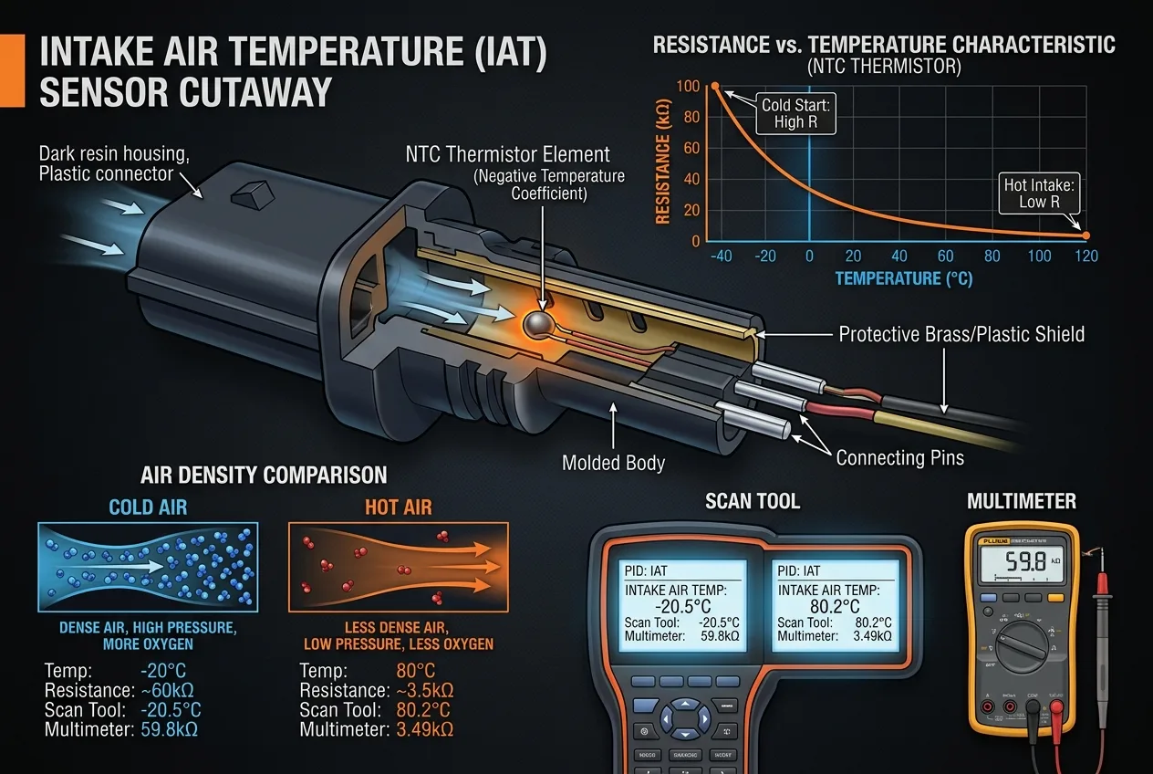
What it does: Measures incoming air temperature. Cold air is dense (more oxygen per volume). Hot air is less dense. The ECU adjusts fuel accordingly.
Location: Often integrated into the MAF or MAP sensor. Can also be standalone.
Testing Method (NTC Thermistor):
- Compare IAT reading to ambient temperature (cold engine, key ON)
- Disconnect sensor, measure resistance
- Compare to manufacturer's resistance/temperature curve
- Gently warm the sensor and verify resistance decreases smoothly
NTC Behavior: As temperature increases, resistance decreases. This is inverse to most electrical components.
Common Codes: P0110–P0114
Warning: Never use a flame or heat gun directly on the sensor. Use controlled heat (hair dryer on low, or warm water bath) and observe gradual resistance change.
Pro Tip: An IAT reading 20°F+ off from ambient indicates a problem. But verify ambient with a separate thermometer—your perception of "room temperature" isn't a calibrated reference.
6. Engine Coolant Temperature Sensor (ECT) — The Cold Start Commander
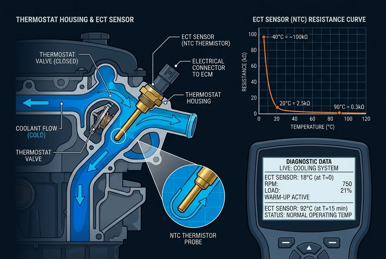
What it does: Measures coolant temperature. The ECU uses this for:
- Cold-start fuel enrichment
- Idle speed control
- Cooling fan activation
- Transmission shift strategy (on some vehicles)
Testing Protocol:
- Cold engine: ECT should match ambient temperature (within a few degrees)
- Warm-up: Monitor scan tool data—temperature should rise smoothly
- Hot engine: Compare ECT to actual coolant temperature (infrared thermometer on thermostat housing)
Multimeter Test:
- Disconnect sensor (engine cold)
- Measure resistance across terminals
- Compare to manufacturer's NTC curve
- Reconnect, start engine, verify scan tool temperature rises steadily
Common Codes: P0115–P0119
Before Replacing:
- Check coolant level (low coolant = erratic readings)
- Verify thermostat operation (stuck open = slow warm-up)
- Inspect wiring for corrosion (common at ECT connectors)
- Check for air pockets in cooling system
Pro Tip: An ECT reading -40°F when it's 70°F outside means an open circuit. An ECT reading 250°F on a cold engine means a short to ground. These extremes are circuit faults, not sensor failures.
7. Knock Sensor (KS) — The Timing Guardian
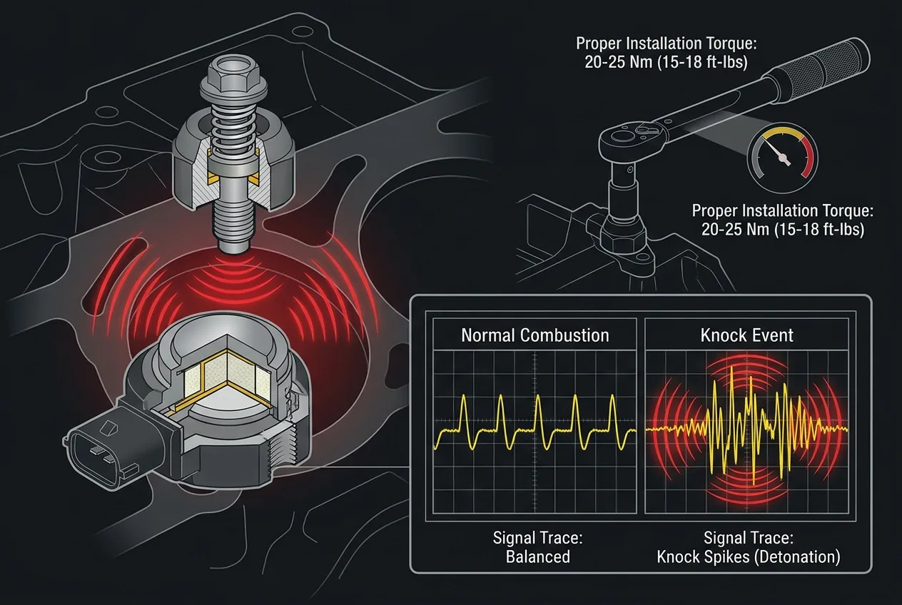
What it does: Detects vibration frequencies characteristic of detonation (knock). The ECU retards timing to protect the engine.
Why It's Tricky: Knock sensors are piezoelectric—they generate voltage from vibration. No vibration = no signal. You can't test them with a static multimeter reading.
Testing Challenges:
- No universal voltage specification
- Resistance testing isn't a valid diagnostic
- Signal is AC, not DC—varies with frequency and amplitude
Approach:
- Visual: Check mounting bolt torque (critical—sensor must be torqued to spec)
- Circuit: Verify continuity from sensor to ECU (per wiring diagram)
- Oscilloscope: Observe signal during engine operation—look for AC activity
- Scan tool: Check for timing retard events (indicating false knock or real knock)
Common Codes: P0325–P0334
Never Do This: Strike the sensor with a tool to "test" it. This can damage the piezoelectric element and doesn't provide meaningful diagnostic information.
Common Misdiagnosis: A loose knock sensor (wrong torque) generates false knock signals, causing timing retard and power loss. The sensor isn't bad—the installation is.
Pro Tip: Check mounting surface cleanliness and bolt torque before replacing. A $0.50 bolt torque check beats a $100 sensor replacement.
8. Oxygen Sensor (O2/Lambda) — The Mixture Judge
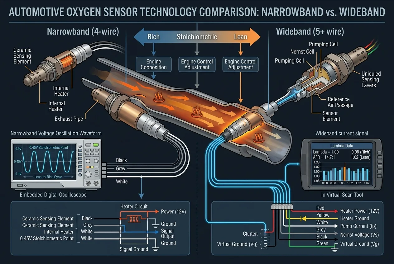
What it does: Measures oxygen content in exhaust. The ECU uses this to:
- Adjust fuel mixture (closed-loop operation)
- Monitor catalytic converter efficiency
- Verify combustion quality
Two Distinct Types—Don't Confuse Them:
| Narrowband (4-wire typical) | Wideband (5+ wire) |
|---|---|
| Signal: 0.1–0.9V oscillating | Signal: Current-based (pump cell) |
| Tests: Voltage swing, response time | Tests: Manufacturer-specific parameters |
| Replacement: Direct voltage correlation | Replacement: Don't apply narrowband tests |
Narrowband Testing:
- Engine at operating temperature, closed-loop enabled
- Backprobe signal wire
- Observe voltage oscillation (should swing between ~0.1V and ~0.9V)
- Verify rapid response to throttle changes (rich/lean transitions)
Wideband Testing:
- Use scan tool lambda data (not direct voltage)
- Verify heater circuit separately
- Compare commanded lambda to actual lambda
- Do not measure wideband cell resistance like a narrowband sensor
Heater Circuit Test (Both Types):
- Disconnect sensor
- Measure heater resistance (typically 2–15 ohms, check spec)
- Verify power and ground at heater circuit (key ON)
Common Codes: P0130–P0167 (varies by sensor position and circuit)
Before Replacing:
- Check for exhaust leaks upstream (false lean reading)
- Verify no intake leaks (false lean condition)
- Check for misfires (contaminate sensor)
- Inspect heater fuse and relay
Pro Tip: A "slow" O2 sensor might be a failing sensor—or it might be a lazy fuel system, a small vacuum leak, or an exhaust leak. Verify mixture control before condemning the sensor.
The Universal 4-Step Diagnostic Method
Every sensor follows this workflow. Skip a step, and you're guessing.
Step 1: Interrogate the ECU
- Read all codes (current and pending)
- Capture freeze frame data (what were the conditions when the fault set?)
- Review live data for related parameters
- Note: A single code is a symptom; multiple codes tell a story
Step 2: Visual Inspection
- Connectors: loose, corroded, damaged pins
- Wiring: chafed, melted, cut, routed incorrectly
- Mounting: loose sensors, damaged reluctor wheels
- Mechanical: vacuum leaks, exhaust leaks, fluid leaks
This step costs nothing and finds 30% of problems.
Step 3: Circuit Verification
- Identify pins from wiring diagram (never guess)
- Verify power and ground (where applicable)
- Measure voltage drop under load (not just open-circuit voltage)
- Check continuity only with power removed
Warning: Never short a 5V reference to ground "to see what happens." You'll damage the ECU.
Step 4: Signal Analysis
| Tool | Best For |
|---|---|
| Multimeter | Power, ground, resistance, basic voltage |
| Oscilloscope | Waveform shape, frequency, intermittent faults |
| Scan tool | Interpreting what the ECU sees, fuel trim analysis |
Compare physical measurement to scan tool data. If they disagree, the circuit (not the sensor) is suspect.
Sensor Quick Reference
| Sensor | Priority Check | Expected Signal | Code Range |
|---|---|---|---|
| CKP | Sync + rotation signal | AC inductive or digital Hall | P0335–P0339 |
| CMP | Cam/crank correlation | AC inductive or digital Hall | P0340–P0349 |
| MAF | Airflow vs. load | Analog, frequency, or digital | P0100–P0104 |
| MAP | Pressure vs. conditions | Typically analog voltage | P0105–P0109 |
| IAT | Temperature plausibility | NTC resistance curve | P0110–P0114 |
| ECT | Warm-up behavior | NTC resistance curve | P0115–P0119 |
| KS | Mounting + vibration signal | Piezoelectric AC | P0325–P0334 |
| O2 | Mixture response + heater | Narrow or wideband | P0130–P0167 |
Safety Rules That Prevent Expensive Mistakes
- Never measure resistance on a powered circuit—you'll damage your meter or the ECU
- Never backprobe without proper pins—piercing wire insulation creates future corrosion points
- Never apply 12V to a 5V reference circuit—ECU damage is expensive
- Respect high voltage—hybrids and EVs have orange cables for a reason
- Keep hands clear of fans, belts, and pulleys—engine running tests require constant awareness
- Exhaust components stay hot—allow cool-down before O2 sensor service
- Verify sensor torque specs—especially knock sensors and CKP/CMP sensors (air gap matters)
The Bottom Line
Diagnostic success isn't about having the most expensive tools. It's about process discipline:
- Read the data (don't guess)
- Inspect visually (free information)
- Verify the circuit (before blaming the part)
- Analyze the signal (confirm your hypothesis)
- Reproduce the fault (prove the fix)
A fault code is a starting point, not a conclusion. The sensor is the last suspect, not the first.
Master the method, and you'll stop throwing parts—and start actually fixing cars.
Related articles
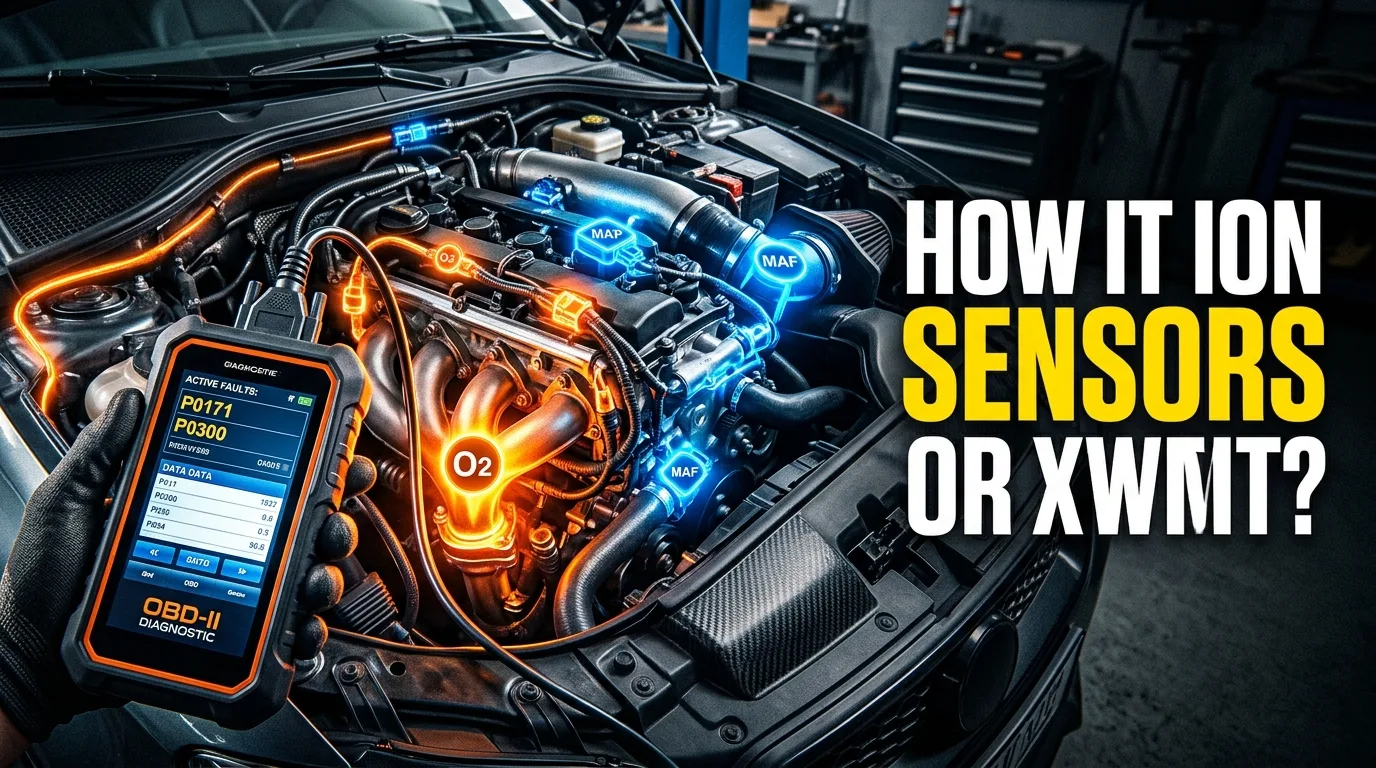
The Ultimate Guide to Engine Sensors: 40+ Types, Functions, and Failure Symptoms (Gasoline & Diesel)
Engine sensors control performance, fuel economy & emissions. Learn 40+ sensor types, failure symptoms, testing methods, and OBD-II codes for gas & diesel engines.
Read the article →
8 Warning Signs Your Gasoline Engine Is About to Fail
Most engine failures don't happen out of nowhere. They send postcards first. A rattle here, a puff of smoke there, a check engine light you decide to ignore until inspection time.
Read the article →
How to Reduce Diesel Fuel Consumption: 10 Practical Tips
Diesel isn't cheap, and if you run a van, a pickup or a small fleet, fuel is probably your single biggest running cost. The good news: most diesel vehicles are burning more than they need to, and a lot of that waste is fixable in an afternoon.
Read the article →
10 Hidden Features in Your Car That Dealerships Rarely Explain
Most of the useful stuff in your car is buried in the owner's manual, and nobody reads the owner's manual. Not the salesperson, not the service advisor, and probably not you. That is fine. I am going to walk you through the features that actually change how you live with a car, the ones that make y…
Read the article →
Diesel Engine: 10 Mistakes Drivers Make Without Knowing It
Diesel engines are tough, and that toughness fools people. A petrol car will often complain loudly when you treat it badly. A diesel just keeps going, quietly accumulating damage until the day it doesn't. That gap between "running fine" and "facing a four-figure repair bill" is where most owners lo…
Read the article →
10 Signs Your Petrol or Diesel Engine Is Starting to Fail
Your engine rarely dies without warning. It whispers first, then talks, then screams. Most drivers only start listening at the screaming stage, which is when the repair bill has already tripled.
Read the article →